JavaScript is required to for searching.
Skip Navigation Links
Exit Print View
Oracle SuperCluster M6-32

Owner's Guide: Installation

search filter icon
search icon

Document Information

Using This Documentation

Product Documentation Library

Feedback

Installing SuperCluster M6-32

Hardware Installation Overview

Weight Specifications

Hardware Installation Task Overview

Hardware Installation Documents

Preparing the Site (Storage Rack and Expansion Racks)

Prepare the Site for the Racks

Storage Rack Components

Physical Specifications

Reviewing Power Requirements

PDU Power Specifications

Facility Power Requirements

PDU Thresholds

Preparing for Cooling

Heat Dissipation Specifications

Airflow Requirements

Perforated Floor Tiles

Environmental Specifications

Preparing the Network

Network Topology

Network Infrastructure Requirements

Compute Server Default Host Names and IP Addresses

Install Cable Drops

Prepare DNS

Cabling SuperCluster M6-32

Compute Server Network Components

Storage Rack Network Components

Cable the ZFS Storage Appliance

ZFS Appliance Power Cord Connection Reference

ZFS Storage Appliance Cabling Reference

Cable IB Switches

Leaf Switch 1 Cabling Reference

Leaf Switch 2 Cabling Reference

IB Switch-to-Switch Cabling Reference

Cable the Ethernet Management Switch

Ethernet Management Switch Cabling Reference

Connect SuperCluster M6-32 to the Facility Networks

Connecting Expansion Racks

Expansion Rack Overview

Expansion Rack Components

Expansion Rack Layouts

Installing Expansion Racks

One Expansion Rack Cabling

Two Expansion Racks Cabling

Three Expansion Racks Cabling

Four Expansion Racks Cabling

Five Expansion Racks Cabling

Six Expansion Racks Cabling

Seven Expansion Racks Cabling

Expansion Rack Default IP Addresses

Understanding Internal Cabling (Expansion Rack)

Oracle ILOM Cabling

Administrative Gigabit Ethernet Port Cabling

Single-Phase PDU Cabling

Three-Phase PDU Cabling (Full Rack)

IB Network Cabling

Glossary

Index

Compute Server Network Components

Use this illustration and table to identify the locations of the network components in the compute server.
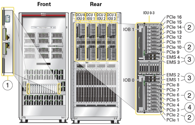
image:An illustration showing the location of network components.
No.
Network Component or Port
Chassis Location
Connector and Cable Type
Links
1
2 SPs, each providing:
  • 1 10/100/10000BASE-T port (NET MGT)

  • 1 serial port (SER MGT)

Front lower bay, SP 0 (left) and SP 1 (right)
NET MGT – RJ-45, use Cat.5 or better cables.

SER MGT – RJ-45, use serial cables.

2
8 or 161 IB HCA PCIe cards (4 cards per IOU, 2 ports per card)
Installed in these slots in all functional IOUs:
  • PCIe 2

  • PCIe 6

  • PCIe 10

  • PCIe 14

16 to 32standard IB connectors supporting cables with QSFP connectors.
3
EMSs (4 per functional IOU), each providing 2 100/1000/100000BASE-T ports
Installed in these slots in all functional IOUs:
  • EMS 1

  • EMS 2

  • EMS 3

  • EMS 4

RJ-45, use Cat6A or better cables.
4
2 or 41 Sun Quad Port GbE PCIe 2.0 Low Profile Adapters, UTP (1 per IOU)
Installed in these slots in all functional IOUs:
  • PCIe 3

RJ-45, use Cat.5 or better cables.

1Quantity is based on the number of IOUs ordered.

Related Information