Scenario: Combining Network Virtualization and Network Resource Management
Network virtualization with network resource management helps you to manage flow control, improve system performance, and configure the network utilization needed to achieve OS virtualization, utility computing, and server consolidation. This section uses a scenario to show how to use network virtualization with network resource management to optimize system performance.
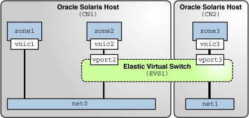
The following figure shows the network virtualization setup that is used in this scenario.
Figure 3 Use Case: Network Virtualization Setup

The setup consists of the following components:
-
Oracle Solaris hosts CN1 and CN2 that are configured with the datalinks net0 and net1 respectively.
-
Oracle Solaris Zones zone1 and zone2 that are configured on CN1 and zone3 that is configured on CN2.
-
Zones zone1, zone2, and zone3 that are configured with the VNICs vnic1, vnic2, and vnic3 respectively.
-
Elastic virtual switch EVS1 that is set up between zone2 on CN1 and zone3 on CN2. Zones zone2 and zone3 are in the same network and hence are configured on the same elastic virtual switch.
-
Virtual ports vport2 and vport3 that are the points of attachment between the VNICs and EVS1.
You can allocate network resources based on the priority and the rate of processing packets of different applications that run on zones. You can use datalink properties and flows to allocate network resources for the VNICs appropriately. This scenario is based on the following assumptions for allocating network resources:
-
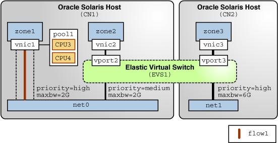
zone1 hosts the applications app1 and app2. You need to configure a flow on vnic1 to isolate traffic and implement control over how packets belonging to the flows use resources. You also need to configure a separate pool of CPUs for vnic1.
-
zone2 hosts the application app3 that communicates with a database on zone3.
-
zone3 hosts a database that communicates with zone2. Because vnic3 receives and transmits more packets than the other VNICs, it uses more bandwidth. So, you need to set a higher bandwidth limit to cap the bandwidth usage of vnic3. You can also set a high priority for packet processing.
Based on these assumptions, the network resources are allocated for the VNICs that are configured on the Oracle Solaris hosts. The following figure shows the allocation of network resources for the VNICs by using the datalink properties and flows.
Figure 4 Use Case: Network Virtualization With Flows and Resource Allocation

This figure shows the datalink and flow properties that are set for the VNICs and flow1. The following table describes these properties and their values.
|