Assemble the DC Input Power Cords
-
Prepare as follows:
- Install a DC power source that meets the server's input power specifications.
-
Obtain DC power cords that meet the server's power cabling specifications.
See DC Power Source, Power Connection, and Grounding Requirements.
- Obtain a crimping tool or a soldering gun and supplies.
- Obtain heat-shrink tubing in colors matching the ground, positive, and negative cord designations.
-
Ensure that no DC power is present on the cords being installed.

Caution - Do not proceed with these instructions until you are sure that there is no voltage present on the DC cords and their power source.
- Route the power cords from the power source to the server.
-
Locate the three wires coming from your DC power source that will be used for the connections to your server.
-
-48V or -60V Return (positive terminal)
-
-48V or -60V (negative terminal)
-
Chassis ground
Note - Depending on the DC power source, the positive terminal might be marked with a positive (+) symbol, and the negative terminal might be marked with a minus (-) symbol. -
-
Strip 1/2 in. (13 mm) of insulation from each of the wires.
Do not strip more than 1/2 in. (13 mm) from each wire. Doing so leaves uninsulated wire exposed from the DC connector after the assembly is complete.
 No.Description11/2 in. (13 mm) maximum
 -
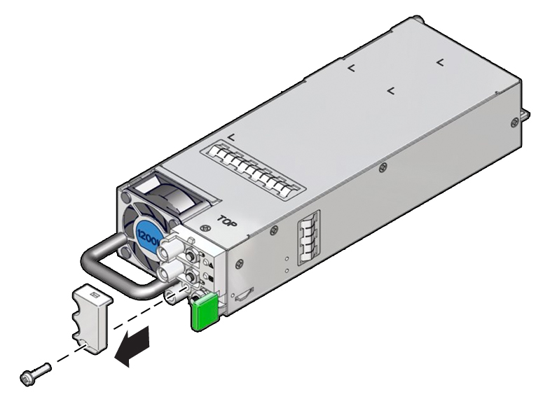
Using a Phillips screwdriver, remove the terminal housing cover.

-
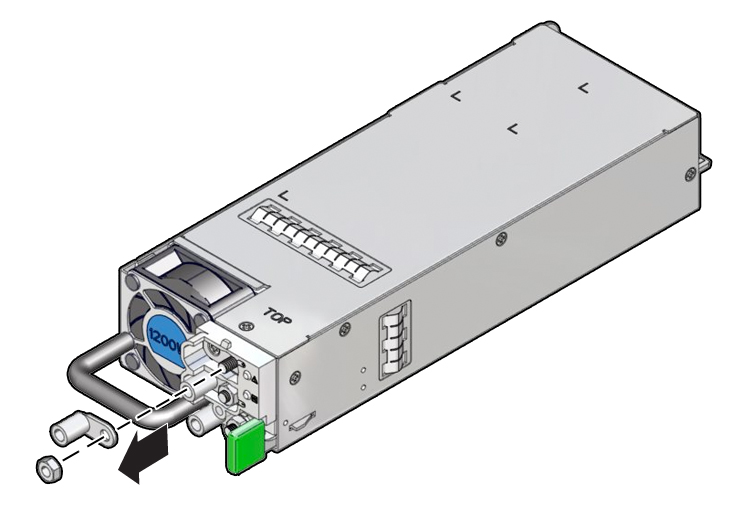
Using a 7mm socket wrench or nut driver, remove the three ring load terminals and nuts.

-
Place heat-shrink tubing over the cords:
- Cut a 4 cm piece of heat-shrink tubing, then slide it over each input wire, using the corresponding color (ground, negative or positive) on each wire.
- Push the tubing at least 15 cm away from the end of the wire, so that crimping or soldering does not damage the tubing.
- Insert the stripped end of a cord into the barrel of a ring terminal, then either crimp the barrel or solder the wire to the inside of the barrel.
- Repeat the procedure for the other two wires.
- Lower the heat-shrink tubing over each of the ring terminal barrels, then shrink fit the tubing with a heat gun.
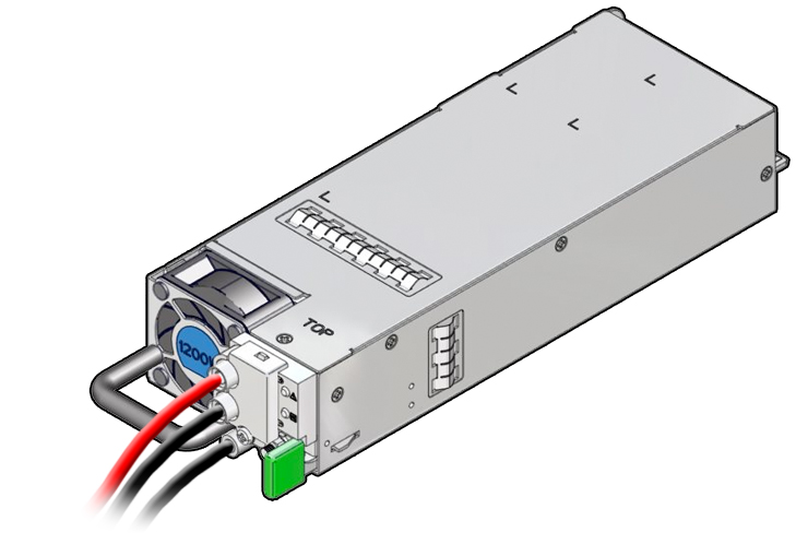
- Observing correct polarity designations for the attached cords, use the lug nuts to install the ring terminal barrels to the three terminal posts.
- Verify that the cords are installed with the correct polarities.
-
Install the terminal housing cover.

-
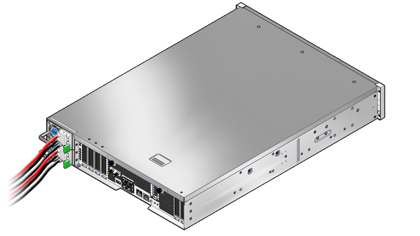
Insert the completed power supply unit into the server.

- Repeat this procedure to create as many DC power supply units as you need for your system.
- Connect the DC power source.