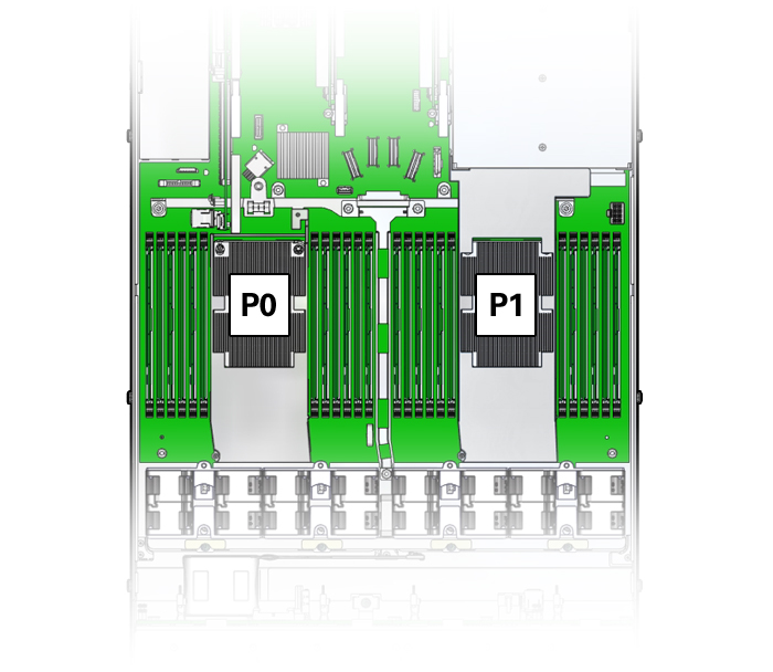
DIMM and Processor Physical Layout
The physical layout of the DIMMs and processor(s) is shown in the following figure. When viewing the server from the front, processor 0 (P0) is on the left.
Each processor, P0 and P1, has twelve DIMM slots organized into six memory channels. Each memory channel contains two DIMM slots: a black DIMM slot (channel slot 0) and a white DIMM slot (channel slot 1).
|
