- Oracle Exadata Storage Server X9-2 EF, HC, and XT Service Manual
- Servicing the Motherboard Assembly
- Remove the Motherboard Assembly
Remove the Motherboard Assembly
-
Prepare the server for service.
- (Optional - Persistent Memory (PMeM) DIMMs only) If your server is configured with PMeM DIMMs, perform Step 6 in Install a DIMM to collect PMeM DIMM serial numbers and matching DIMM slot numbers. This facilitates placing PMeM DIMMs into their correct DIMM slots during the motherboard replacement procedure.
- Power off the server, disconnect the power cords from the power supplies, and label each power cord that you disconnect.
- Extend the server into the maintenance position.
- Attach an antistatic wrist strap to your wrist, and then to a metal area of the chassis.
- Remove the server top cover.
-
If present on the HC or XT server, remove the Oracle Storage 12 Gb SAS PCIe
RAID HBA, Internal card and its associated super capacitor.
See Remove the Internal HBA Card and HBA Super Capacitor.
Note:
After you remove the HBA super capacitor, remove the HBA super capacitor tray by squeezing the plastic hinges together and lifting the tray from the chassis. -
Remove the following reusable components:
Caution:
During the motherboard removal procedure, it is important to label power supplies with the slot numbers from which they were removed (PS0, PS1). This is required because the power supplies must be reinstalled into the slots from which they were removed; otherwise, the server key identity properties (KIP) data might be lost. When a server requires service, the KIP is used by Oracle to verify that the warranty on the server has not expired. For more information on KIP, see Key Identity Properties (KIP) Automated Update.-
Fan modules
See Remove a Fan Module.
-
Fan tray
See Remove the Fan Tray.
-
Air baffle
-
PCIe cards
See Remove a PCIe Card.
-
SAS storage drive cables (if present)
-
NVMe cables (if present)
See Remove NVMe Cables.
-
Power supplies
-
-
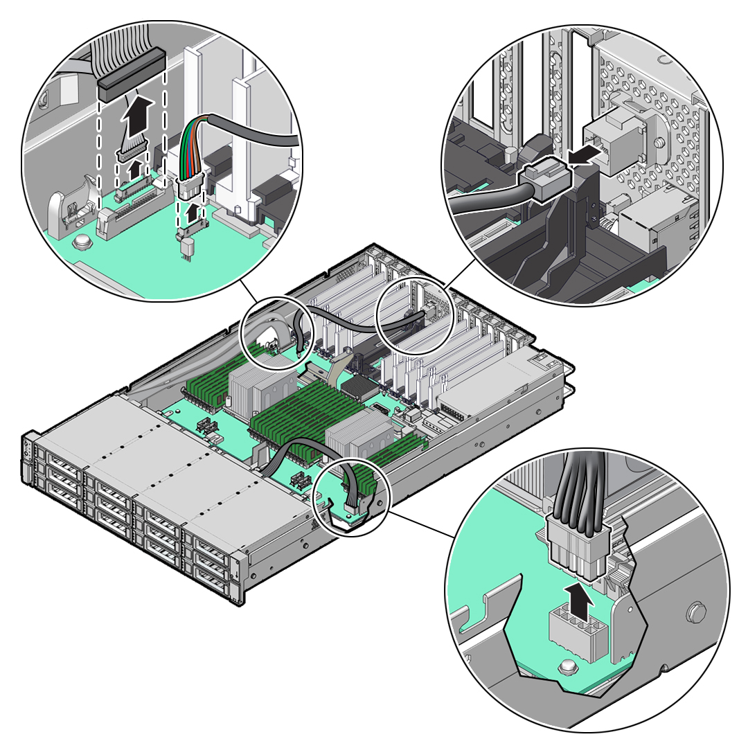
Disconnect the following cables from the motherboard:
-
Front LED indicator module ribbon cable
-
Disk backplane auxiliary signal cable
-
Disk backplane power cable
-
SER MGT RJ-45 serial cable
Disconnect and remove the SER MGT RJ-45 cable between the motherboard and back panel.
-
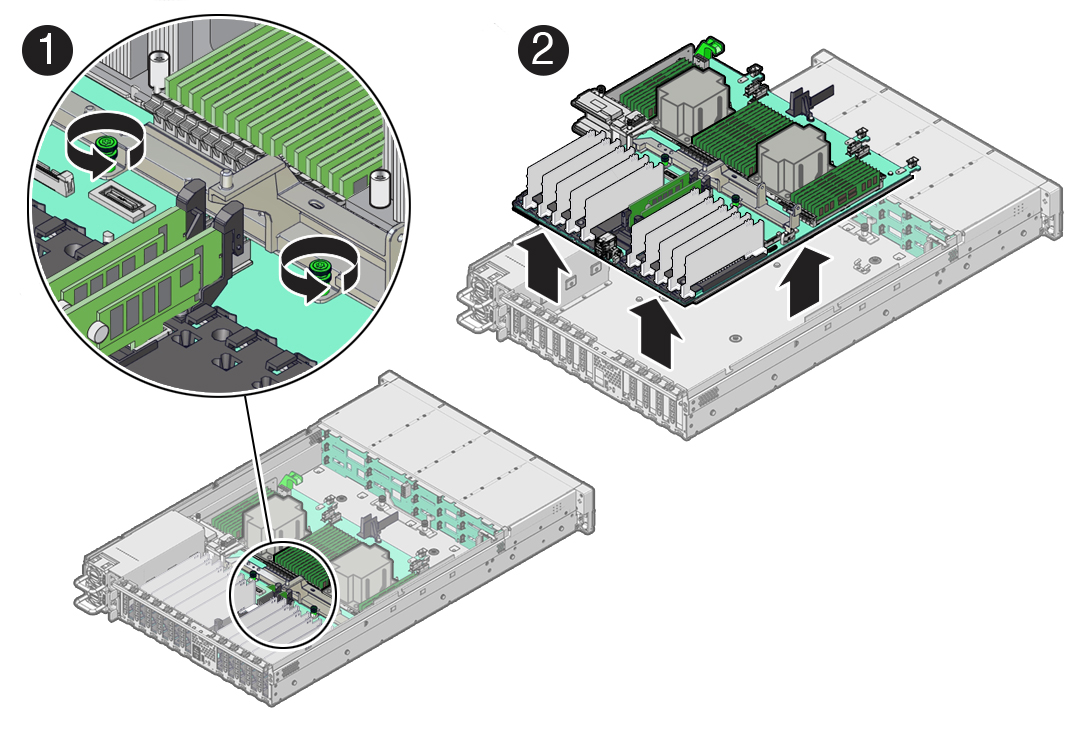
- Using a Torx T25 screwdriver, loosen the two captive screws that secure
the motherboard mid-wall to the chassis [1].
-
With the server in the extended maintenance position, remove the motherboard
from the server with all reusable components that populate the motherboard in
place [2].
- Carefully slide the motherboard forward, and while holding the motherboard mid-wall, lift it out of the chassis.
- Place the motherboard assembly on an antistatic mat, and next to the replacement motherboard.
-
Remove the following reusable components from the motherboard and install them
onto the replacement motherboard.
-
DIMMs
See Identify and Remove a DIMM and Install a DIMM.
Note:
Install the DIMMs only in the slots (connectors) that correspond to the slots from which they were removed. Performing a one-to-one replacement of the DIMMs significantly reduces the possibility that the DIMMs will be installed in the wrong slots. If you do not reinstall the DIMMs in the same slots, server performance might suffer and some DIMMs might not be used by the server.Caution:
Persistent Memory (PMeM) DIMMs must retain their slot locations due to PMeM interleaving. -
M.2 flash riser SSDs
See Remove a Flash Riser Board and Install a Flash Riser Board.
-
- Remove the processors from the failed motherboard.
- Remove the processor socket covers from the replacement motherboard and
install the processors.
- Grasp the processor socket cover finger grips (labeled REMOVE)
and lift the socket cover up and off the processor socket.
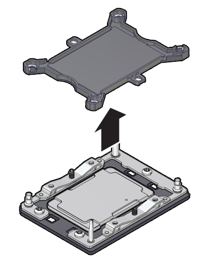
- Install a processor into the socket from which you removed the
processor socket cover. See Install a Processor.
- Repeat Step 9.a and Step 9.b to remove the second processor socket cover from the replacement motherboard and install the second processor.
- Grasp the processor socket cover finger grips (labeled REMOVE)
and lift the socket cover up and off the processor socket.
- Install the processor socket covers on the faulty motherboard.
Caution:
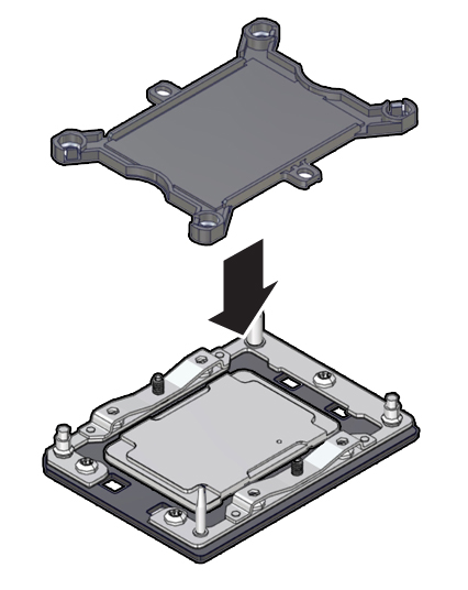
The processor socket covers must be installed on the faulty motherboard; otherwise, damage might result to the processor sockets during handling and shipping.- Align the processor socket cover over the processor socket
alignment posts. Install the processor socket cover by firmly pressing down on
all four corners (labeled INSTALL) on the socket cover.
You will hear an audible click when the processor socket cover is securely attached to the processor socket.
- Repeat Step 10.a to install the second processor socket cover on the faulty motherboard.
- Align the processor socket cover over the processor socket
alignment posts. Install the processor socket cover by firmly pressing down on
all four corners (labeled INSTALL) on the socket cover.
-
Check to see if the replacement motherboard has a locate light pipe
installed.
-
If it does, no action is necessary.
-
If it does not, perform the following steps.
-
Check to see if the replacement motherboard came with a light pipe. It
should be in a separate plastic bag.
-
If you find a replacement light pipe, skip to Step 11.b.
-
If you do not find a replacement light pipe, perform the following steps to remove the light pipe from the faulty motherboard.
- Insert a flat tool such as a screwdriver or penknife blade
between the light pipe housing and the light pipe.
Caution:
Equipment damage. The light pipe is fragile. Handle it carefully.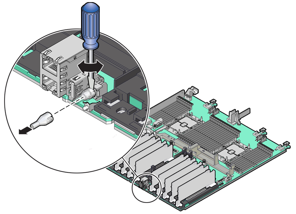
- Twist the tool back and forth to release the light pipe from the housing.
- Pull the light pipe away from the housing.
-
- Install the light pipe on the replacement motherboard.
- Match the rectangular holes on the outside of the light pipe with the
retaining clips on the housing.
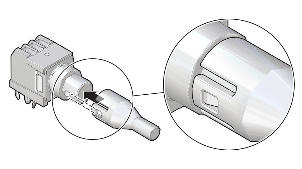
- Push the light pipe onto the housing until the clips latch in the holes.
- Match the rectangular holes on the outside of the light pipe with the
retaining clips on the housing.
-
Related Topics: