| Skip Navigation Links | |
| Exit Print View | |

|
Sun Datacenter InfiniBand Switch 648 Topic Set |
Documentation, Support, and Training
Understanding Administrative Commands
Monitoring the InfiniBand Fabric
Controlling the InfiniBand Fabric
Understanding Signal Routing Through the Switch
Understanding Switch Startup and Component Addition
Understanding ILOM on the Switch
Switching Between the ILOM Shell and the Linux Shell
Controlling ILOM Targets (CLI)
Upgrading the Switch Firmware Through ILOM (CLI)
Administering ILOM (Web Interface)
Access ILOM From the Web Interface
Monitoring ILOM Targets (Web Interface)
Controlling ILOM Targets (Web Interface)
Upgrading the Switch Firmware Through ILOM (Web Interface)
Understanding InfiniBand Cabling
Understanding Switch Specifications
Understanding the Installation
Fabric Card and Line Card Fillers
Suggested Tools for Installation
Antistatic Precautions for Installation
Installing the InfiniBand Software Stack
Install the HPC Software Suite
Remove the Shipping Carton Contents
Unsecure the Chassis From the Pallet
Install the Chassis in the Rack
Inspecting the Midplane Condition
Midplane Fabric Card Connector Nomenclature
Inspect the Pins on the Rear Side of the Midplane
Midplane Line Card Connector Nomenclature
Inspect the Pins on the Front Side of the Midplane
Inspecting the Fabric Cards Condition
Fabric Card Handling Guidelines
Inspect the Fabric Card Chassis Condition
Inspect the Fabric Card Retainer Bolts Condition
Inspect the Fabric Card XBOW Connectors Condition
Inspecting the Line Cards Condition
Inspect the Line Card Chassis Condition
Inspect the Line Card Retainer Bolts Condition
Inspect the Line Card XBOW Connectors Condition
Inspect the Line Card CXP Connectors Condition
Inspecting the InfiniBand Cables Condition
Inspect the InfiniBand Cables Hardware Condition
Inspect the InfiniBand Cables Connector Condition
Install the Midplane Stiffener
Install the Fabric Cards or Fabric Card Fillers
Access the CMC From the Serial Management Port
Set the Initial UBoot Parameters
Access the CMC From the Network Management Port
Display the CMC FRU ID Information
Verify the Power Supply Status
Display the Power Supply FRU ID Information
Create the guid.txt File for Installation
Display the Fabric Card FRU ID Information
Display the Line Card FRU ID Information
Attach Cables to the CXP Connectors
Display the InfiniBand Cable FRU ID Information
Verifying the InfiniBand Fabric
Discover the InfiniBand Fabric Topology
Perform Diagnostics on the InfiniBand Fabric
Validate the InfiniBand Fabric and Report Errors
Understanding Service Procedures
Servicing the Fabric Cards and Fabric Card Fillers
Servicing the InfiniBand Cables
Doing Supportive Software Tasks
Understanding Switch-Specific Commands
There are three positions to install the switch into the rack, bottom, middle, and top. The rack does not accommodate more than three switches.
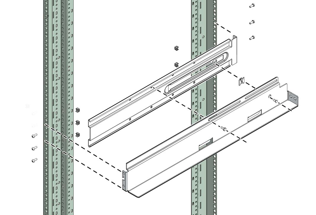
Note - For this procedure, the term cabinet holes refers to the holes in the posts of the cabinet. For the Sun Rack II cabinet, these holes are square. The holes are numbered from 1 starting at the very bottom. Hole 2, 3, 4, and so on, are the second, third, fourth, and so on, hole from the bottom. The numbering scheme printed on the posts is not used.
Note - If you are installing fewer than three switches, favor the bottom and middle positions.
 | Caution - Do not install any rail-mounted equipment in the Sun Datacenter InfiniBand Switch 648 rack. The Sun Datacenter InfiniBand Switch 648 switches must be loaded into the rack from the bottom up. |
See the table in Installation Sequence.
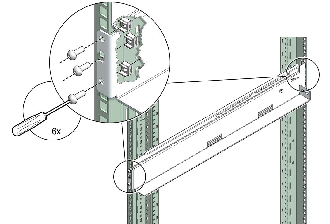
where x, y, and z are the respective cabinet holes:
2, 4, and 5 for bottom mounting
36, 38, and 39 for middle mounting
70, 72, and 73 for top mounting

where t, u, and v are the respective cabinet holes:
2, 5, and 6 for bottom mounting
36, 39, and 40 for middle mounting
70, 73, and 74 for top mounting
