JavaScript is required to for searching.
Skip Navigation Links
Exit Print View
Sun Datacenter InfiniBand Switch 648 Topic Set
search filter icon
search icon

Document Information

Preface

Related Documentation

Documentation, Support, and Training

Third-Party Web Sites

Sun Welcomes Your Comments

Administration

Administering the Switch

Understanding Administrative Commands

Monitoring the Switch

Monitoring the InfiniBand Fabric

Controlling the Switch

Controlling the InfiniBand Fabric

Diagnosing a Problem

Identifying the Problem

Troubleshooting the Switch

Understanding Signal Routing Through the Switch

Understanding Switch Startup and Component Addition

Switch GUIDs Overview

Remote Management

Understanding ILOM on the Switch

ILOM Documentation

ILOM Overview

Supported Features

Understanding ILOM Targets

Installing the ILOM Firmware

Firmware Layout

rupgrade_tool Application

Download the ILOM Firmware

Install the ILOM Firmware

Administering ILOM (CLI)

CLI Overview

Access ILOM From the CLI

Switching Between the ILOM Shell and the Linux Shell

Monitoring ILOM Targets (CLI)

Controlling ILOM Targets (CLI)

Upgrading the Switch Firmware Through ILOM (CLI)

Administering ILOM (Web Interface)

Web Interface Overview

Access ILOM From the Web Interface

Monitoring ILOM Targets (Web Interface)

Controlling ILOM Targets (Web Interface)

Upgrading the Switch Firmware Through ILOM (Web Interface)

Understanding ILOM Commands

cd Command

create Command

delete Command

dump Command

exit Command

help Command

load Command

set Command

show Command

version Command

Installation

Preparing the Site

Routing Service Cables

Understanding InfiniBand Cabling

Understanding Switch Specifications

Installing the Switch

Understanding the Installation

Supported Configurations

Fabric Card Distribution

Line Card Distribution

Fabric Card and Line Card Fillers

Installation Preparation

Suggested Tools for Installation

Antistatic Precautions for Installation

Installation Responsibilities

Installer Experience

Installation Sequence

Installing the InfiniBand Software Stack

Install the HPC Software Suite

Unpacking the Chassis

Remove the Shipping Carton Contents

Unsecure the Chassis From the Pallet

Preparing the Chassis

Install the Rail Assemblies in the Rack

Install the Cable Trees

Install the Cable Curves

Install the Chassis in the Rack

Inspecting the Components

Inspecting the Midplane Condition

Midplane Fabric Card Connector Nomenclature

Inspect the Pins on the Rear Side of the Midplane

Midplane Line Card Connector Nomenclature

Inspect the Pins on the Front Side of the Midplane

Inspecting the Fabric Cards Condition

Fabric Card Features

Fabric Card Handling Guidelines

Inspect the Fabric Card Chassis Condition

Inspect the Fabric Card Retainer Bolts Condition

Inspect the Fans Condition

Inspect the Fabric Card XBOW Connectors Condition

Inspecting the Line Cards Condition

Line Card Features

Line Card Handling Guidelines

Inspect the Line Card Chassis Condition

Inspect the Line Card Retainer Bolts Condition

Inspect the Line Card XBOW Connectors Condition

Inspect the Line Card CXP Connectors Condition

Inspecting the InfiniBand Cables Condition

InfiniBand Cable Features

Inspect the InfiniBand Cables Hardware Condition

Inspect the InfiniBand Cables Connector Condition

Installing the Components

Install the Midplane Stiffener

Install the Fabric Cards or Fabric Card Fillers

Remove the Midplane Stiffener

Install the Line Cards

Powering On the CMCs

Power Supply Addresses

Power Supply Status LEDs

CMC Addresses

CMC Status LEDs

Attach Management Cables

Attach Power Cords

Accessing the CMC

Access the CMC From the Serial Management Port

Set the Initial UBoot Parameters

Access the CMC From the Network Management Port

Verify the CMC Status

Display the CMC FRU ID Information

Verify the Power Supply Status

Display the Power Supply FRU ID Information

Powering On the Fabric Cards

Fabric Card Addresses

Fabric Card Status LEDs

Enable the Fabric Cards

Create the guid.txt File for Installation

Power On the Fabric Cards

Verify the Fabric Card Status

Display the Fabric Card FRU ID Information

Powering On the Line Cards

Line Card Addresses

Line Card Status LEDs

Enable the Line Cards

Power On the Line Cards

Verify the Line Card Status

Display the Line Card FRU ID Information

Connecting InfiniBand Cables

CXP Connector Addresses

CXP Connector Status LEDs

Attach Cables to the CXP Connectors

Check Link Status

Display the InfiniBand Cable FRU ID Information

Verifying the InfiniBand Fabric

Discover the InfiniBand Fabric Topology

Perform Diagnostics on the InfiniBand Fabric

Validate the InfiniBand Fabric and Report Errors

Service

Servicing the Switch

Understanding Service Procedures

Servicing the Power Supplies

Servicing the CMCs

Servicing the Fans

Servicing the Fabric Cards and Fabric Card Fillers

Servicing the InfiniBand Cables

Servicing the Line Cards

Doing Supportive Software Tasks

Reference

Command Reference

Understanding Switch-Specific Commands

Understanding CLIA Commands

Understanding InfiniBand Software Commands

Index

Install the Line Cards


Caution

Caution - Installing the line card is a methodical task and cannot be rushed. To prevent damage to the line card or the midplane XBOW connectors, pay close attention to the procedure and work slowly.


  1. Identify the prerequisite and subsequent tasks you must perform in conjunction with this procedure, to install the switch.

    See the table in Installation Sequence.

  2. Lift the line card from the work surface and orient it horizontally, with the link LEDs across the bottom.
  3. Insert the line card into the chassis at slot 0.

    Ensure that the line card is square to the chassis and not skewed.
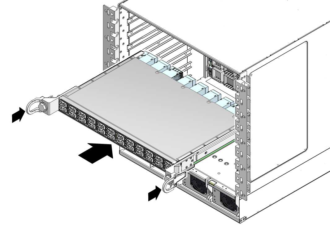

    Illustration shows the line card being inserted.

    Note - Once the line card is about halfway into the slot, it is no longer necessary to bear the weight of the line card.


  4. Continue to slide the line card in, maintaining a squared orientation.

    When you feel resistance, stop.

  5. While pressing the line card in with one hand, rotate the retainer bolts clockwise by hand so that they engage.

    When you feel resistance in the retainer bolts, stop.
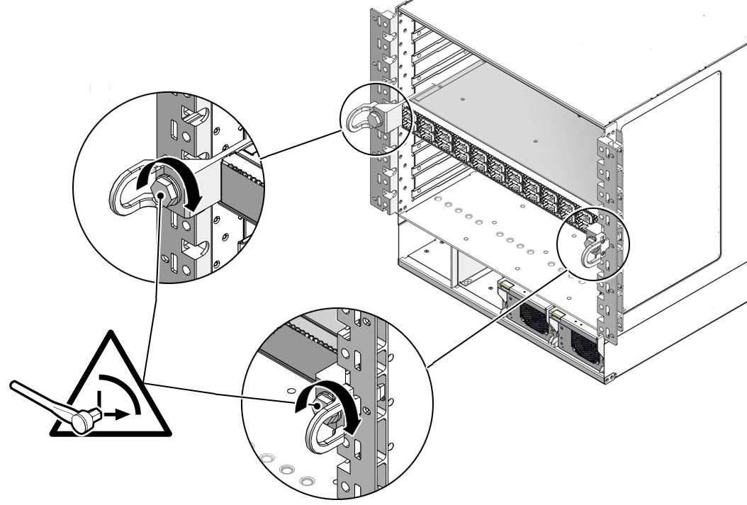
  6. Using a 20 mm socket and ratchet, turn the left retainer bolt 1/4 turn clockwise.
    Illustration shows the line card bolts being secured.
  7. Turn the right retainer bolt 1/4 turn clockwise.

    Caution

    Caution - Do not turn the retainer bolts more than 1/4 revolution each time. Turning more than 1/4 turn damages the line card and midplane XBOW connectors.


  8. Repeat Step 6 and Step 7 about 12 times until you feel resistance to turning and the line card is flush to the front of the chassis.
  9. Give each retainer bolt a torque of 2.0 ft-lb (0.27 kg-m).
  10. Turn the left retainer bolt 1/4 turn counter-clockwise.
  11. Turn the right retainer bolt 1/4 turn counter-clockwise.
  12. Repeat Step 10 and Step 11 twice to relieve board deflection.
  13. Verify that the line card is properly seated in the slot.
  14. Repeat Step 2 through Step 13 for each line card to be installed.

    Install the cards into the following slots in the following sequence:

    0, 1, 2, 3, 4, 5, 6, 7, 8

  15. Install the line card fillers into the vacant slots.
    1. Grasp the handles at each end of the line card filler and lift the filler to the vacant slot.
    2. Slide the filler into the chassis until it stops.
    3. While pressing the filler in with one hand, rotate the retainer bolts clockwise by hand so that they engage.

      When you feel resistance in the retainer bolts, stop.

    4. Repeat Step a through Step c for all remaining vacant slots.
  16. Power on the CMCs.

    See Powering On the CMCs.

Related Information