Chapter 1 Designing Data Integrator Projects
Sun Data Integrator is an extract, transform, and load (ETL) tool for data warehousing or data migration.Data Integrator is designed to manage and orchestrate high-volume, high-performance data transformation from within the SOA tier. Data Integrator, along with the Java CAPS platform, offers a comprehensive enterprise integration infrastructure. Sun Data Integrator is an enterprise module optimized for extracting , transforming , and loading bulk data between files and databases. It provides connectivity to a vast range of heterogeneous and diversified data sources including non relational data sources. It provides an ETL development and runtime environment that is fully integrated into Java CAPS and NetBeans and optimized for handling very large record sets.
The following topics provide instructions on how to design and use Data Integrator projects.
What You Need to Know
These topics provide information you should know before you start customizing a master index application.
What You Need to Do
The topics provide instructions on how to create and configure Data Integrator components.
Creating ETL Collaborations
Configuring ETL Collaborations
About Data Integrator
Data Integrator is an Extract/Transform/Load (ETL) tool for data warehousing or data migration. It is designed to manage and orchestrate high-volume, high-performance data transformation from within the SOA tier. Data Integrator, along with Java CAPS platform, offers a comprehensive enterprise integration infrastructure. Sun Data Integrator is an enterprise module optimized for extracting , transforming , and loading bulk data between files and databases. It provides connectivity to a vast range of heterogeneous and diversified data sources including non relational data sources. It provides an ETL development and runtime environment that is fully integrated into Java CAPS and NetBeans and optimized for handling very large record sets.
Extracting, Transforming, Loading: ETL
ETL stands for Extract, Transform, and Load. ETL programs periodically extract data from source systems, transforms the data into common format, and then loads the data into the target data store or warehouse. ETL process brings together and combines data from multiple source systems into a data warehouse, enabling all users to work off a single, integrated set of data.
-
Extract The process of reading data from specified source database and extracting a desired subset of data.
-
Transform The process of transforming the data in the required form so that it can be placed into another database. Transformation occurs by using rules or lookup tables or by combining with other data
-
Load The process of writing/loading the data into the target database.
Sun Data Integrator Overview
Extracting, Transforming, and Loading: ETL
ETL stands for Extract, Transform, and Load. ETL programs periodically extract data from source systems, transforms the data into common format, and then loads the data into the target data store or warehouse. ETL processes bring together and combine data from multiple source systems into a data warehouse or other target database, enabling all users to work off a single, integrated set of data.
-
Extract – The process of reading data from specified source database and extracting a desired subset of data.
-
Transform – The process of transforming the data into the required form so that it can be placed into another database. Transformation occurs by using rules or lookup tables or by combining with other data.
-
Load: The process of writing or loading the data into the target database.
Sun Data Integrator Methodology
Extraction, Transform, and Load (ETL) is a data integration methodology that extracts data from data sources, transforms and cleanses the data, then loads the data in a uniform format into one or more target data sources.
Data Integrator provides high-volume extraction and loading of tabular data sets for Java CAPS, NetBeans, or OpenESB, projects, or as a standalone product. You can use Data Integrator to acquire a temporary subset of data for reports or other purposes, or acquire a more permanent data set for the population of a data mart or data warehouse. You can also use ETL for database type conversions or to migrate data from one database or platform to another.
Data Integrator applies the following ETL methodology:
-
Extraction: The input data is extracted from data sources. Using Data Integrator, the data can be filtered and joined from multiple, heterogeneous sources, which results in a desired subset of data suitable for transformation.
-
Transformation: Data Integrator applies the operators specified for the process to transform and cleanse the data to the desired state. Sun Data Integrator supports normalization and parsing of certain data.
-
Load: The transformed data is loaded into one or multiple databases or data warehouses.
Sun Data Integrator Features
The following are the list of features for Sun Data Integrator:
-
Requires little database expertise to build high performing ETL processes.
-
Metadata auto discovery enables user to design ETL processes faster.
-
Takes advantage of database bulk, no-logging tuning where applicable for faster data warehouse loads.
-
Support for creating automatic joins based Primary Key and Foreign Key relationships, and creates code to ensure data integrity.
-
Takes advantage of database engine by pushing as much of the workload on to the target and source database.
-
Supports extensive non-relational data formats
-
Transforms, filters, and sorts at the source where appropriate.
-
Supports data cleansing operators to ensure data quality. Provides a dictionary driven system for complete parsing of names and addresses of individuals and organizations, products, and locations. Supports data normalization and de-normalization.
-
Converts data into a consistent, standardized form to enable loading to a conformed target databases.
-
Supports built–in data integrity checks.
-
Supports data type conversion, null value handling, and customized transformation.
-
Provides a robust error handler to ensure data quality and a comprehensive system for reporting and responding to all error events.
-
Supports change management functions or versioning.
-
Allows concurrent or parallel processing of multiple source data streams.
-
Supports full refresh and incremental extraction.
-
Is fully integrated with NetBeans to provide a complete development environment.
-
Supports Data Federation, enabling you to use SQL to define ETL processes.
-
Provides near real-time click-stream data warehousing (in conjunction with the JDBC Binding Component).
-
Supports Enterprise Resource Project and Customer Relation Manager data sources in conjunction with various components from Java CAPS.
-
Provide platform independence and scalability to enterprise data warehousing applications.
-
Allows you to define complex transformations using built-in transformation objects.
-
Allows you to schedule ETL sessions based on time or on the occurrence of a specified event (in conjunction with Java CAPS components).
-
Can participate as a partner in BPEL business processes. Sun Data Integrator exposes the ETL process as web service.
-
Can extract data from outside a firewall in conjunction with FTP and HTTP Connectors.
-
Provides reporting and analysis of transformations that failed or were rejected, and then allows you to resubmit them after correcting the data.
-
Provides extensive reporting of the results of ETL sessions, including automatic notification of significant failures of the process.
Sun Data Integrator Architecture
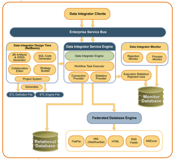
Sun Data Integrator has three primary components:
Figure 1–1 Data Integrator Architecture
Sun Data Integrator Design-Time Components
The primary components of the Data Integrator design-time are the ETL Collaboration Editor and the project system.
Data Integrator Editor
The Data Integrator Editor allows you to configure your ETL processes by modifying the source code or by using a graphical editor. It has many predefined data transformation, validation, and cleansing functions, and also allows you to add user-defined functions. This editor is a design-time component that you use to design the ETL collaborations and to create the artifacts that can be deployed as a Data Integrator Service Engine.
The Data Integrator editor contains various modules and functions embedded in it, including the following:
-
Model (SQL Framework)
-
View (JGo Graph Library view)
-
Controller
-
Wizards (New ETL File wizard and Mashup wizard)
-
Database Evaluators
-
Code Generator
Sun Data Integrator Project System
The project system acts as a container for holding the ETL files and provides ant-based build support. Building the project creates two types of artifacts: those related to the Service Engine and those related to the ETL Engine. For building the ETL Engine artifacts, the project system delegates the responsibility from the ETL file to the code generation module of the Data Integrator Editor. The project system builds the Service Engine artifacts on its own. Service Engine artifacts are the files etlmap.xml and jbi.xml. The jbi.xml file contains information about the provisioning and consuming endpoint related to the service unit. The etlmap.xml contains the map of the endpoint name and the engine file to be used for the particular endpoint. When an ETL service endpoint gets a request , the ETL Service Engine picks up the correct engine file using etlmap.xml and invokes the ETL Engine with this file.
Data Integrator Service Engine
The Data Integrator Service Engine is an implementation of a Java Business Integration (JBI) service engine and is compliant with JSR 208. When the service engine is deployed to a JBI container, the service unit (SU) JAR file that is produced by a Data Integrator project is consumed by the Data Integrator Service Engine.
The ability of the Sun Data Integrator Service Engine to expose ETL operations as web services makes the tool suitable for business integration applications based on a Service Oriented Architecture (SOA). This engine is specially designed to work with high volume data with high performance. TheData Integrator Service Engine package is an embedded database engine and has the ability to execute SQL on non-database data sources.
The Data Integrator Service Engine includes the ETL Engine and the ETL Service Engine.
ETL Engine
The ETL Engine is responsible for executing the ETL operations that were designed using the ETL Collaboration Editor or Data Integrator Wizard. The ETL Engine parses the engine file, substitutes all SQL scripting with the runtime parameters if any, and then starts the execution. SQL scripts generated during the design time can be parameterized and can be substituted in the runtime. The ETL task manager creates a thread for each task defined using the ETL task thread. The task manager waits for dependent tasks and maintains the work flow that was specified in the engine file. The ETL Engine supports batch processing and uses prepared statements to provide better performance.
ETL Service Engine
The ETL Service Engine is an optional component. This component exposes the ETL operations as web services and also handles the service requests and responses. This component is installed separately.
Data Integrator Monitor
The Data Integrator Monitor is a web application that you can use to monitor the progress and statistics of your ETL collaborations. When the ETL Engine executes the engine file, a task is defined for updating the statistics. The ETL Engine creates an Axion database table for keeping track of the collaboration statistics and updates it to track the progress of the ETL operation. The Axion table is queried by the ETL Monitor and the results are displayed in the web console.
On the Data Integrator Monitor, you can view detailed information about each record and about rejected records. You can also view a summary of the process. The monitor also provides the ability to purge obsolete messages.
Data Integrator Recovery
Data Integrator has the capability to:
-
Persist the incoming requests using derby/Oracle data source.
-
Restore the requests in case the engine or the application server goes down.
-
Retry in case the source or target connections are down when the Data Integrator project executes, and remain able to successfully run the project when the database comes back up.
Creating Sun Data Integrator Projects
The following tasks describe how to create and add components to a Sun Data Integrator project using the Data Integrator Wizard.
Connecting to Source and Target Databases
Before you can select databases and database tables to extract data from and load data to, you need to create and connect to the databases to use. Sun Data Integrator supports JDBC-compliant databases, flat files, and data mashup services. You only need to define the connections for relational databases. If you are using flat files as your source, you do not need to create or connect to a database. The wizard provides the ability to connect to multiple source files.
Connecting to a JDBC-Compliant Database
This step requires that the database drivers for the database platforms you are working with are installed. Some database drivers are already installed by default, but you might need to add the database driver depending on which database platform you are using. For example, if you are using Oracle or Microsoft SQL Server, you need to copy the driver to the application server and add it to the Services window.
 To Connect to a JDBC-Compliant Database
Before You Begin
Make sure the database you are connecting to has already been created and is running. If the database drivers for the platforms you are using have not been installed to app_server/lib, copy the drivers to that location.
-
In the NetBeans Services window, expand Databases.
-
If you do not see the driver for the database you are using, copy the driver from your database installation to AppServer_Home/lib and then do the following:
-
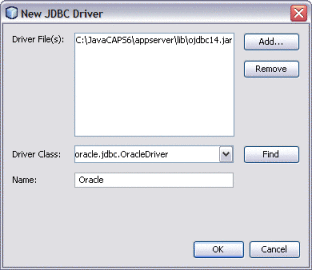
Right-click Drivers, and select New Driver.
-
On the New JDBC Driver dialog box, click Add.
-
Browse to and open the JAR or ZIP file you copied to the application server libdirectory.
-
Accept the default driver class or type in a new one. If no driver is entered, click Find to have the wizard search for an appropriate class.
-
Enter a name for the driver.
-
Click OK.
The new database driver appears under Drivers in the Services window.
-
-
Right-click the new driver, and select Connect Using.
-
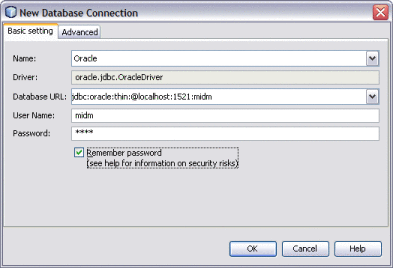
In the New Database Connection dialog box, do the following:
-
Enter the database connection URL.
Note –Different database platforms use different connection URLs. Refer to your database documentation for the format to use.
-
Enter the user name and password to use to log on to the database.
-
Select Remember Password.
-
To select a specific schema in the database, click the Advanced tab and then click Get Schemas.
A list of available schemas appears for you to choose from.
-
Click OK.
A new database connection appears under Databases.
-
-
Right-click the new database, and select Connect.
Creating and Connecting to Data Mashup Services
If you want to use more than one data source for the data integration process, you can create a Data Mashup Service. Data mashup allows you to select multiple data sources of varying types and combine them into one target database. Source data can reside in files on your network or on the web in HTML, RSS, or Web Row Set format.
Note –
New in Java CAPS Release 6 Update 1, you can specify multiple data sources using the Data Integrator Wizard. If you are using multiple source files, you can either create the mashup here or you can use the Data Integrator Wizard to specify the sources directly.
 To Create a Mashup Database for Source Data
-
In the NetBeans main menu, select Tools, point to Virtual Database, and then select Create Virtual Database.
-
On the New Virtual Database wizard, enter a name for the database and then click Finish.
-
Click OK on the confirmation dialog box that appears.
-
In the NetBeans main menu, select Tools, point to Virtual Database, and then select Add External Tables.
The Add External Tables Wizard appears.
-
Select the database you just created and then click Next.
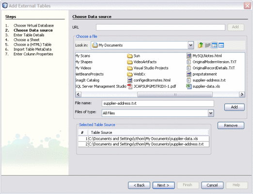
The Choose Data Source window appears.
-
To add data sources, do any of the following:
-
If the data source is on the web (such as HTML or Web Row Set), enter a URL for the data source and click Add.
-
If the data source is a file on your network, brows to and select the input file. Click Add.
-
Repeat the above steps for each data source.
Tip –If you add a data source in error, highlight it in the table and then click Remove.
-
Click Next.
The Enter Tables Details window appears.
-
-
Enter table information for the table specified in the Table Name field, and then click Next.
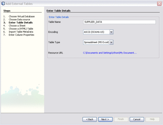
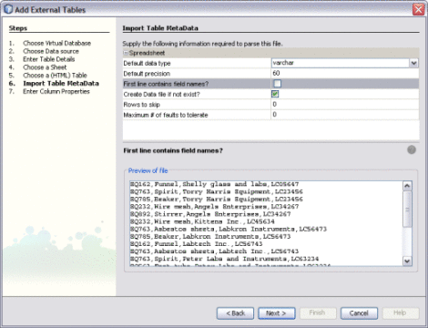
Depending on the type of file you selected, the Choose a Sheet, Choose a (HTML) Table, or Import Table MetaData window appears.
-
If the Choose a Sheet or Choose a (HTML) Table window appears, do the following:
-
If necessary, modify the information required to parse the data source.
The available options on this window vary depending on the type of data source. For more information about the properties you can modify, see Virtual Database Table Metadata Options.
-
Click Next.
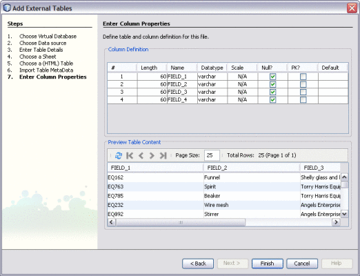
The Enter Column Properties window appears.
-
Modify the properties for the database columns in the upper portion of the window.
Tip –For more information about column properties, see Virtual Database Column Properties. If your data source does not contain field names, you should customize the column names for clarity.
-
Preview the source data in the lower portion of the window.
-
Do one of the following:
-
Right–click the new database and select Connect.
Virtual Database Table Metadata Options
When you add external tables to a virtual database, you can configure the metadata for each data source. All metadata properties are listed below, but some might not be available depending on the type of data source you are adding.
|
Property |
Description |
Values |
|---|---|---|
|
Default Data Type (or WIZARDDEFAULT SQLTYPE) |
The default data type used for all fields in the data source (you can change the default in subsequent steps). |
varchar numeric time timestamp |
|
Record Length (or WIZARDDEFAULT PRECISION) |
The maximum length of a record in number of characters. This option must be appropriate for the selected data type and must be the same for all fields. |
Any integer greater than or equal to 0. |
|
Field Count |
The number of fields per record. |
Any integer greater than 1. |
|
Default Precision |
The length of the database columns for each field. You can modify this value for each field at a later time. |
For numeric data types, enter <= 38. For time/timestamp data types, enter the length of the format. |
|
Type of XML File |
An indicator of whether the XML file is read/write or read only. |
READWRITE READONLY |
|
ROWNAME | ||
|
Record Delimiter |
The character that separates each record. |
newline (LF) carriage return (CR) CR LF CR LF or LF semicolon (;) comma (,) tab pipe (|) |
|
Field Delimiter |
The character that separates each field in a record. Select User Defined if the character does not match any of the other options in the menu. |
comma tab semicolon pipe User Defined |
|
User-defined Field Delimiter |
The custom character that separates each field in a record. Use this field to specify a delimiter that is not a comma, tab, semicolon, or pipe. Unless you select User Defined for the Field Delimiter, this field is ignored. | |
|
Text Qualifier |
A qualifier used to indicate text. |
none double quote: “ single quote: ” |
|
First line contains field names? |
An indicator of whether the names specified in the header row are used as field names or whether Data Integrator should assign default field names. |
Select the check box to use column header names from the file. Deselect the check box if the file does not contain a header row. |
|
Create data file if not exist? | ||
|
Header Offset |
The number of bytes to skip before reaching the start of the first record. This value is ignored if the First line contains field names? check box is deselected. |
Any integer greater than or equal to 0. |
|
Rows to Skip (or Records to Skip) |
The number of rows or records to skip before the starting row or record for the data set. Specify 0 (zero) to include all rows or records from the source. |
Any integer greater than or equal to 0. |
|
Maximum # of Faults to Tolerate |
The number of faults that can occur before Data Integrator generates an error message. |
Any integer greater than or equal to 0. |
|
Trim Whitespace |
An indicator of whether to strip white space and tabs from the beginning and end of a string. |
Select the check box to trim white space. Deselect the check box to leave white space in the string. |
Virtual Database Column Properties
When you add external tables to a virtual database, you can configure the column attributes for each data source. All column properties are listed below.
|
Property |
Description |
Values |
|---|---|---|
|
# |
The number of each column (this value cannot be modified). | |
|
Length |
The length for each column in the virtual database. |
Any integer greater than 0. This value must be appropriate for the data type. |
|
Name |
The name of each column. |
An unlimited number of characters. |
|
Datatype |
The type of data stored in each field. |
varchar time numeric timestamp |
|
Scale |
The number of digits to the right of the decimal point in a number field; for example, 9876.543 has a scale of 3. |
An integer greater than 0. |
|
Null |
An indicator of whether the field can be null. |
Select the check box if the field can be null or deselect it if the field cannot be null. |
|
PK |
An indicator of whether the column is a primary key. |
Select the check box if the column is a primary key or deselect it if the column is not a primary key. |
|
Default |
Any default data to add to a column. |
Creating a New Data Integrator Project
Before you can begin to define and configure the components and ETL processes to use for your data integration you need to create a new project of the type Data Integrator Module.
 To Create a New Project
-
Right-click in the NetBeans Projects window, and select New Project.
The New Project Wizard appears.
-
Under Categories, select SOA.
-
Under Projects, select Data Integrator Module.
-
Click Next.
-
Enter a unique name and a location for the project.
-
If this is not a main project, deselect Set as Main Project.
-
Click Finish.
The new project appears in the Projects window.
Next Steps
Create an ETL Collaboration following the instructions provided under Creating an ETL Collaboration Using the Wizard. You can also create an ETL Collaboration from scratch, but the wizard provides a quick and easy way to generate most of the collaboration code.
Creating an ETL Collaboration Using the Wizard
Note –
The Data Integrator Wizard was enhanced in Java CAPS 6 Update 1. The instructions in this topic might differ from what is available in Release 6.
You can use the Data Integrator Wizard to create as much or as little of the ETL collaboration as you want. You can exit the wizard at any time once the basic framework is defined. After you complete the wizard, you can open the collaboration for further configuration.
The wizard provides three options for the collaboration:
-
Basic Extract – Allows you to generate an ETL Collaboration that extracts, transforms, and loads data between JDBC, virtual (mashup), and flat-file databases. To create a basic collaboration, follow the instructions under Creating a Basic ETL Collaboration.
-
Advanced Extract – Allows you to generate an ETL Collaboration that extracts, transforms, and loads data between data sources and targets when there are multiple sources of different types. This option can also be used for creating an MDM staging database using a Sun Master Index schema to generate the database tables. The staging database can then be used by the Data Cleanser, Data Profiler, and Initial Bulk Match and Load tool for a Sun Master Index. To create an advanced collaboration or a staging database for a master index application, follow the instructions under Creating an Advanced ETL Collaboration. To create a staging database for a master index application, follow the instructions under Creating an ETL Collaboration for a Master Index Staging Database.
-
Bulk Loader – Allows you to generate an ETL Collaboration that loads delimited data in a flat file that is structurally identical to a JDBC-compliant target database. This is specifically designed to load the data images produced by the Bulk Matcher into a master index database. To create a bulk loader collaboration for a master index application, follow the instructions under Creating a Bulk Loader ETL Collaboration.
Creating a Basic ETL Collaboration
Note –
The Data Integrator Wizard was enhanced in Java CAPS 6 Update 1. The instructions in this topic might differ from what is available in Release 6.
A basic collaboration allows you to transfer data from a single data source to a data target. If you have multiple sources, you can create a virtual database before creating the basic collaboration. See Creating and Connecting to Data Mashup Services for more information. You could also use the Advanced option of the wizard instead.
You can click Finish at any time during the wizard to generate a collaboration with the information you specified to that point. Then you can complete the configuration using the ETL Collaboration Editor.
 To Create a Basic ETL Collaboration
Before You Begin
Complete the following tasks:
-
Connecting to Source and Target Databases (if your source or target data is stored in a relational or virtual database)
-
On the NetBeans Projects window, expand the new Data Integrator project and right-click Collaborations.
-
Point to New, and then select ETL.
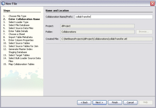
The New File Wizard appears with the Name and Location window displayed.
-
Enter name for the collaboration.
-
Click Next.
-
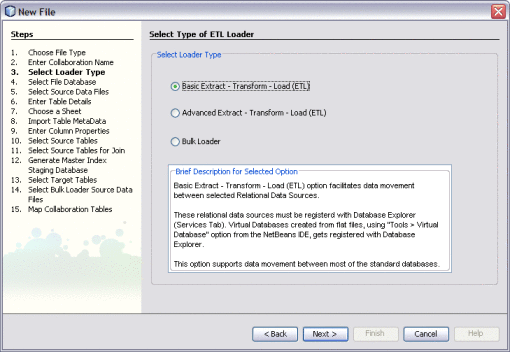
On the Select Type of ETL Loader window on the New File Wizard, select Basic Extract – Transform – Load (ETL).
-
Click Next.
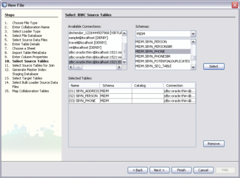
The Select Source Tables window appears.
-
To select the source data, do the following:
-
Under Available Connections, select the database that contains the data to be extracted.
-
Under Schemas, select the name of the database schema that contains the data to be extracted.
Data Integrator automatically selects a schema based on the login information. You only need to change this field if you are using a different schema.
-
Under Schemas, select the tables containing the source data and then click Select.
Tip –You can use the Shift and Control keys to select multiple tables at once. If you add a table in error, select the table in the lower portion of the window and click Remove.
-
Click Next.
The Select Source Tables for Join window appears.
-
-
To define join conditions, do the following. If there are no join conditions, click Next.
-
Under Available Tables, select the tables to join, and then click the right arrow to add them to the Selected Tables list.
-
In the Preview panel, click the drop-down menu at the top of the join box and select the type of join to use from one of the following options:
-
Inner – Use this if all tables to be joined contain the same column.
-
Left Outer – Use this if the results should always include the records from the left table in the join clause.
-
Right Outer – Use this if the results should always include the records from the right table in the join clause.
-
Full Outer – Use this if the results should always include the records from both the right and left tables in the join clause.
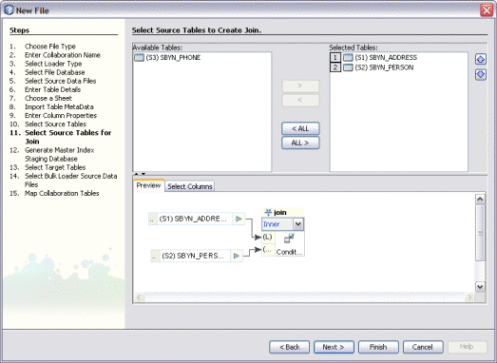
-
-
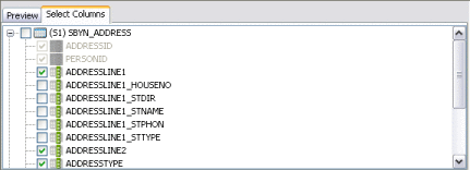
To specify columns to exclude from each joined table, click the Select Column tab in the Preview panel, expand the table list, and deselect any columns to exclude.
-
Click Next.
The Select Target Tables window appears.
-
-
To choose the target tables to load the extracted data into, do the following:
-
Under Available Connections, select the database that contains the schema to load the data into.
-
Under Schemas, select the schema that contains the tables to load the data into.
-
Under Schemas, select the tables that will contain the target data and then click Select.
Tip –You can use the Shift and Control keys to select multiple tables at once. If you add a table in error, select the table in the lower portion of the window and click Remove.
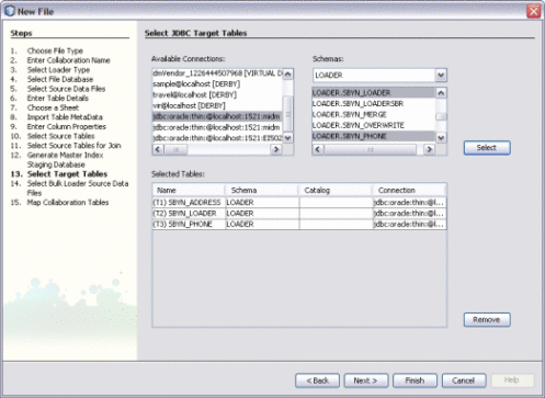
-
Click Finish.
The new ETL collaboration appears in the Projects window, and the Collaboration Editor opens with the source tables displayed on the left and target tables displayed on the right.
-
Next Steps
You can further configure the ETL collaboration using the ETL Collaboration Editor. For more information, see Configuring ETL Collaborations.
Creating an Advanced ETL Collaboration
Note –
The Data Integrator Wizard was enhanced in Java CAPS 6 Update 1. The instructions in this topic might differ from what is available in Release 6.
An advanced collaboration allows you to transfer data from multiple types of data sources to a data target. This procedure describes how to create an advanced collaboration using the automated wizard. Depending on the type of data source and the options you use, the wizard skips certain unnecessary steps. This option might product multiple ETL collaborations depending on the number of target tables.
You can click Finish at any time during the wizard to generate a collaboration with the information you specified to that point. Then you can complete the configuration using the ETL Collaboration Editor.
 To Create an Advanced ETL Collaboration
Before You Begin
Complete the following tasks:
-
Connecting to Source and Target Databases (if your source or target data is stored in a relational or virtual database)
-
On the NetBeans Projects window, expand the new Data Integrator project and right-click Collaborations.
-
Point to New, and then select ETL.
The New File Wizard appears with the Name and Location window displayed.
-
Enter name for the collaboration.

-
Click Next.
-
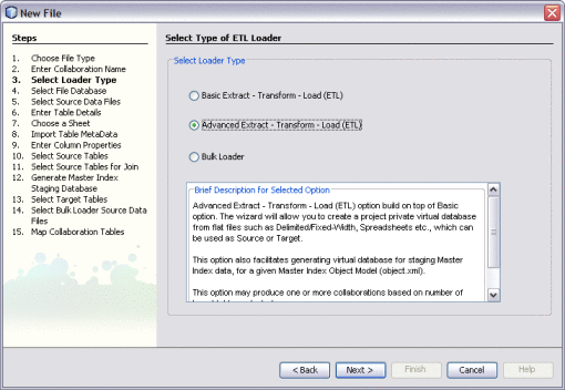
On the Select Type of ETL Loader window on the New File Wizard, select Advanced Extract – Transform – Load (ETL).
-
Click Next.
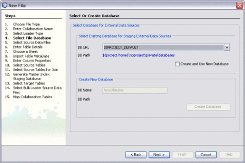
The Select or Create Database window appears.
-
To specify a staging database to use for external data sources (for this project only), do one of the following:
-
Select an existing database to use from the DB URL field.
-
Select Create and Use New Database, enter a name for a new database in the DB Name field, and then click Create Database. Select the new database in the DB URL field.
Note –This database is required and is used for internal processing only.
-
-
Click Next.
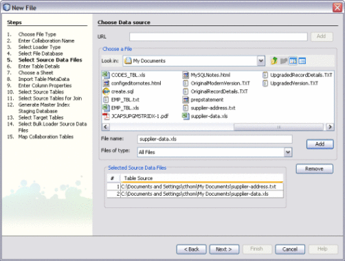
The Choose Data Source window appears.
-
Do one of the following:
-
If you do not have any file data sources, click Next and skip to step 15 (choosing JDBC data sources).
-
To specify a file data source using a URL, enter the URL and click Add.
-
To specify a file data source that is stored on your network, browse for and select a file containing source data in the Choose a File box, and then click Add.
-
Repeat the above two steps until all file data sources are selected.
-
-
Click Next.
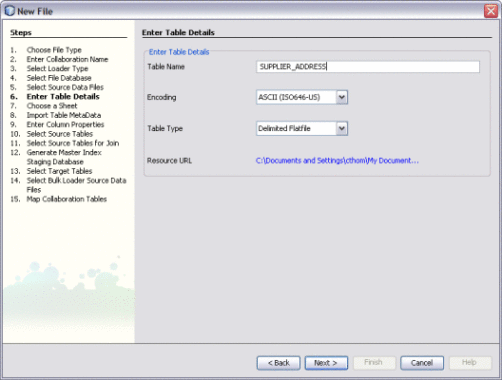
The Enter Table Details window appears, with the information for the first data file displayed.
-
If necessary, modify the table name, the type of data encoding, and the type of document that contains the source data.
Data Integrator automatically fills in these fields based on the information from the previous window, so the existing values should be correct.
-
Click Next.
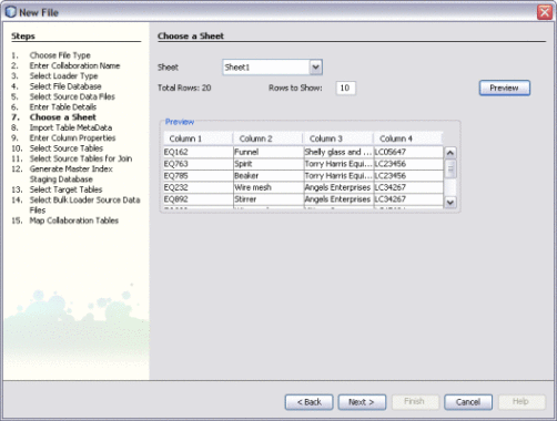
If the data file is a spreadsheet, the Choose a Sheet window appears; otherwise, the Import Table MetaData window appears.
-
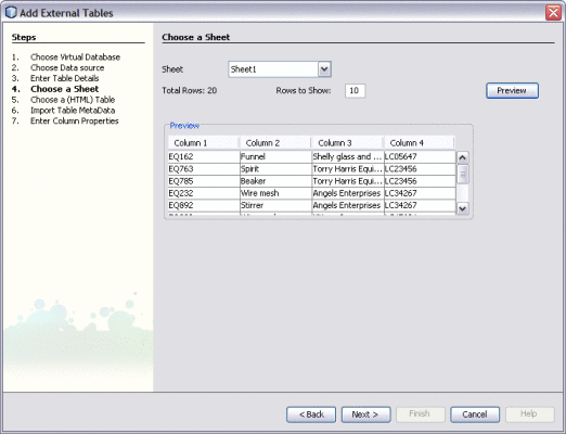
If the Choose a Sheet window appears, select the name of the sheet in the spreadsheet that contains the source data, and then click Next.
Tip –To view the contents of a sheet, click the Preview button.
-
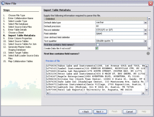
When the Import Table Metadata window appears, modify the information about the data file as needed.
Data Integrator automatically fills in this information, but you might need to customize it. For more information about the properties you can configure, see Virtual Database Table Metadata Options.
-
Preview the information in the bottom portion of the window, and then click Next.
The Enter Column Properties window appears.
-
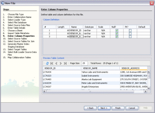
In the upper portion of the window, customize any of the column properties.
For more information about these properties, see Virtual Database Column Properties.
-
Preview the information in the lower portion of the window, and then click Next.
-
Do one of the following:
-
If you selected multiple file data sources, the wizard returns to the Enter Table Details window with the attributes for a different file displayed. Repeat the above steps beginning with step 7.
-
If all the files you specified are configured, a dialog box appears confirming the database table creation. Click OK on the dialog box and continue to the next step.
The Select JDBC Source Tables window appears.
-
-
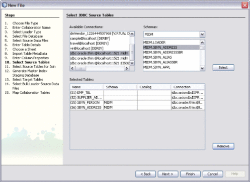
If you specified file data sources, they are already listed under Selected Tables here. Click Next if you have no JDBC data sources to specify, or do the following to specify a JDBC data source:
-
Under Available Connections, select the database that contains the source data.
-
If there are multiple schemas in the database, select the schema to use.
-
Under Schemas, select the tables that contain the source data and then click Select.
-
Click Next.
If there are tables to join, the Select Source Tables for Join window appears; otherwise, the Generate Target Database window appears.
-
-
To define join conditions, do the following. If there are no join conditions, click Next and skip to step 17.
-
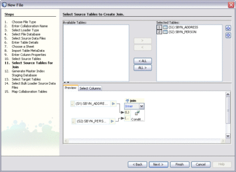
Under Available Tables, select the tables to join, and then click the right arrow to add them to the Selected Tables list.
-
In the Preview panel, click the drop-down menu at the top of the join box and select the type of join to use from one of the following options:
-
Inner – Use this if all tables to be joined contain the same column.
-
Left Outer – Use this if the results should always include the records from the left table in the join clause.
-
Right Outer – Use this if the results should always include the records from the right table in the join clause.
-
Full Outer – Use this if the results should always include the records from both the right and left tables in the join clause.
-
-
To specify columns to exclude from each joined table, click the Select Column tab in the Preview pane and deselect any columns to exclude.
-
Click Next.
The Generate Target Database Master Index Model window appears. Using this page is described in a separate topic, Creating an ETL Collaboration for a Master Index Staging Database.
-
-
Click Next.
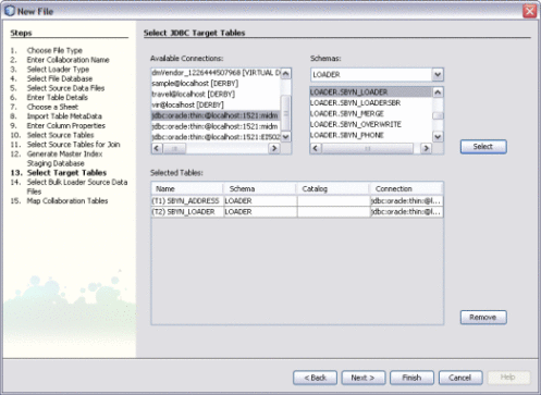
The Select JDBC Target Tables window appears.
-
To choose the target tables to load the extracted data into, do the following:
-
Under Available Connections, select the database that contains the schema to load the data into.
-
Under Schemas, select the schema that contains the tables to load the data into.
-
Under Schema, select the tables that will contain the target data and then click Select.
Tip –You can use the Shift and Control keys to select multiple tables at once. If you add a table in error, select the table in the lower portion of the window and click Remove.
-
-
Click Next.
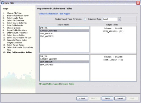
The Map Selected Collaboration Tables window appears.
-
To map source and target data, do the following:
-
To disable constraints on the target tables, select Disable Target Table Constraints.
-
Select the SQL statement type to use for the transfer. You can select insert, update, or both.
-
For each target table listed on the right, select one or more source tables from the list directly to the left of the target table. These are the source tables that will be mapped to the target in the collaboration.
Note –If you do not specify a mapping here, the source tables do not appear in the ETL collaboration. You can add the source tables directly to the collaboration using the Select Source and Target Tables function. To select multiple source tables for one target, hold down the Control key while you select the required source tables. If you select multiple source tables for one target, the source tables are automatically joined.
-
-
Click Finish.
The new ETL collaboration appears in the Projects window. If multiple collaboration are created, they are given the name you specified for the collaboration with a target table name appended.
Next Steps
You can further configure the ETL collaboration using the ETL Collaboration Editor. For more information, see Configuring ETL Collaborations.
Creating an ETL Collaboration for a Master Index Staging Database
Note –
The Data Integrator Wizard was enhanced in Java CAPS 6 Update 1. The instructions in this topic might differ from what is available in Release 6.
The Data Integrator Wizard helps you create and populate a staging database that stores the legacy data to be loaded into a master index database so you can cleanse and load the data in bulk. Data Integrator generates the staging database based on the object structure defined for the master index, so the data is automatically presented in a format that the Data Cleanser, Data Profiler, and Bulk Matcher can read. This procedure describes how to create the staging database using the automated wizard. Depending on the type of data source and the options you use, the wizard skips certain unnecessary steps.
You can click Finish at any time during the wizard to generate a collaboration with the information you specified to that point. Then you can complete the configuration using the ETL Collaboration Editor.
 To Create an ETL Collaboration for a Master Index
Staging Database
Before You Begin
Complete the following tasks:
-
Connecting to Source and Target Databases (if your source or target data is stored in a relational or virtual database)
-
On the NetBeans Projects window, expand the new Data Integrator project and right-click Collaborations.
-
Point to New, and then select ETL.
The New File Wizard appears with the Name and Location window displayed.
-
Enter name for the collaboration.

-
Click Next.
-
On the Select Type of ETL Loader window on the New File Wizard, select Advanced Extract – Transform – Load (ETL).

-
Click Next.
The Select or Create Database window appears.
-
To specify a staging database to use for external data sources (for this project only), do one of the following:
-
Select an existing database to use from the DB URL field.
-
Select Create and Use New Database, enter a name for a new database in the DB Name field, and then click Create Database. Select the new database in the DB URL field.
Note –This database is required and is used for internal processing only.

-
-
Click Next.
The Choose Data Source window appears.
-
Do one of the following:
-
If you do not have any file data sources, click Next and skip to step 15 (choosing JDBC data sources).
-
To specify a file data source using a URL, enter the URL and click Add.
-
To specify a file data source that is stored on your network, browse for and select a file containing source data in the Choose a File box, and then click Add.
-
Repeat the above two steps until all file data sources are selected.

-
-
Click Next.
The Enter Table Details window appears, with the information for the first data file displayed.
-
If necessary, modify the table name, the type of data encoding, and the type of document that contains the source data.
Data Integrator automatically fills in these fields based on the information from the previous window, so the existing values should be correct.

-
Click Next.
If the data file is a spreadsheet, the Choose a Sheet window appears; otherwise, the Import Table MetaData window appears.
-
If the Choose a Sheet window appears, select the name of the sheet in the spreadsheet that contains the source data, and then click Next.
Tip –To view the data in a sheet, click the Preview button.

-
When the Import Table Metadata window appears, modify the information about the data file as needed.
Data Integrator automatically fills in this information, but you might need to customize it. For more information about the properties you can configure, see Virtual Database Table Metadata Options.

-
Preview the information in the bottom portion of the window, and then click Next.
The Enter Column Properties window appears.
-
In the upper portion of the window, customize any of the column properties.
For more information about these properties, see Virtual Database Column Properties.

-
Preview the information in the lower portion of the window, and then click Next.
-
Do one of the following:
-
If you selected multiple file data sources, the wizard returns to the Enter Table Details window with the attributes for a different file displayed. Repeat the above steps beginning with step 7.
-
If all the files you specified are configured, a dialog box appears confirming the database table creation. Click OK on the dialog box and continue to the next step.
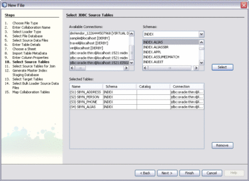
The Select Source Tables window appears.
-
-
If you specified file data sources, they are already listed under Selected Tables. Click Next if you have no JDBC data sources to specify, or do the following to specify a JDBC data source:
-
Under Available Connections, select the database that contains the source data.
-
If there are multiple schemas in the database, select the schema to use.
-
Under Schemas, select the tables that contain the source data and then click Select.
-
Click Next.
If there are tables to join, the Select Source Tables for Join window appears; otherwise, the Generate Target Database window appears.
-
-
To define join conditions, do the following. If there are no join conditions, click Next and skip to step 17.
-
Under Available Tables, select the tables to join, and then click the right arrow to add them to the Selected Tables list.
-
In the Preview panel, click the drop-down menu at the top of the join box and select the type of join to use from one of the following options:
-
Inner – Use this if all tables to be joined contain the same column.
-
Left Outer – Use this if the results should always include the records from the left table in the join clause.
-
Right Outer – Use this if the results should always include the records from the right table in the join clause.
-
Full Outer – Use this if the results should always include the records from both the right and left tables in the join clause.

-
-
To specify columns to exclude from each joined table, click the Select Column tab in the Preview pane and deselect any columns to exclude.
-
Click Next.
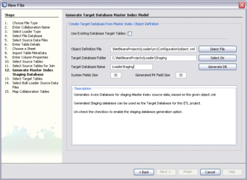
The Generate Target Database Master Index Model window appears.
-
-
To create the staging database, do the following:
-
Deselect the check box for Use Existing Database Target Tables.
-
In the Object Definition File field, browse to and select the object.xml file generated for the Master Index project.
Note –This file is located in NetBeansProjects_Home/Project_Name/src/Configuration.
-
In the Target Database Folder field, select or enter the path where you want to store the database.
-
In the Target Database Name field, enter a name for the database.
-
Click Generate Database.
-
-
Click Next.
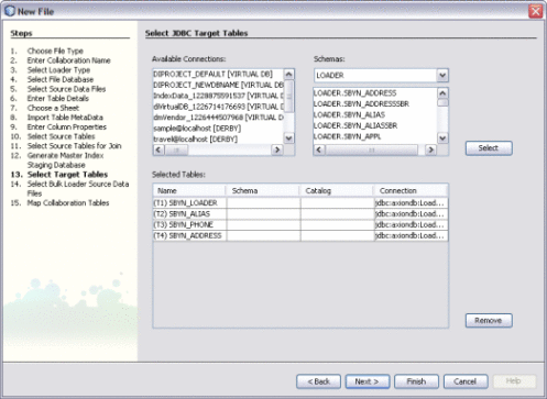
The Select JDBC Target Tables window appears. The target tables to load the extracted data into are already listed under Available Connections. It is not recommended you change these.
-
Click Next.
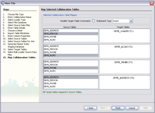
The Map Selected Collaboration Tables window appears.
-
To map source and target data, do the following:
-
To disable constraints on the target tables, select Disable Target Table Constraints.
-
Select the SQL statement type to use for the transfer. You can select insert, update, or both.
-
For each target table listed on the right, select one or more source tables from the list directly to the left of the target table. These are the source tables that will be mapped to the target in the collaboration.
Note –If you do not specify a mapping here, the source tables do not appear in the ETL collaboration. You can add the source tables directly to the collaboration using the Select Source and Target Tables function. To select multiple source tables for one target, hold down the Control key while you select the required source tables. If you select multiple source tables for one target, the source tables are automatically joined.
-
-
Click Finish.
The new ETL collaboration appears in the Projects window. If multiple collaboration are created, they are given the name you specified for the collaboration with a target table name appended. To load the data into the staging database, run each of the collaborations. Make sure you are connected to both databases first.
Next Steps
You can further configure the ETL collaboration using the ETL Collaboration Editor. For more information, see Configuring ETL Collaborations.
Creating a Bulk Loader ETL Collaboration
Note –
The Data Integrator Wizard was enhanced in Java CAPS 6 Update 1. The instructions in this topic might differ from what is available in Release 6.
You can use the Data Integrator Wizard to generate the Bulk Loader for a master index application. The Bulk Loader loads data that has already been cleansed, standardized, and matched into a master index database. The source files for the Bulk Loader are those generated by the Bulk Matcher.
 To Create a Bulk Loader ETL Collaboration
Before You Begin
-
Complete the steps under Creating a New Data Integrator Project.
-
Make sure the master index database is running, and that your NetBeans IDE is connected to the master index database.
-
In order to specify the source files for the Bulk Loader, you need to run the Bulk Matcher first. For more information see, Loading the Initial Data Set for a Sun Master Index.
-
On the NetBeans Projects window, expand the new Data Integrator project and right-click Collaborations.
-
Point to New, and then select ETL.
The New File Wizard appears with the Name and Location window displayed.
-
Enter name for the collaboration.

-
Click Next.
-
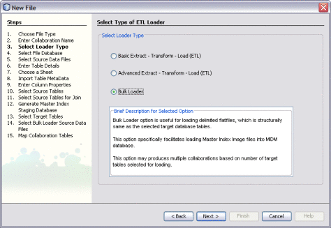
On the Select Type of ETL Loader window on the New File Wizard, select Bulk Loader.
-
Click Next.
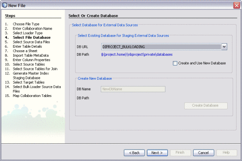
The Select or Create Database window appears.
-
To specify a staging database to use for external data sources (for this project only), do one of the following:
-
Select an existing database to use from the DB URL field.
-
Select Create and Use New Database, enter a name for a new database in the DB Name field, and then click Create Database. Select the new database in the DB URL field.
Note –This database is required and is used for internal processing only.
-
-
Click Next.
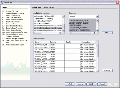
The Select JDBC Target Tables window appears.
-
To choose the target tables to load the extracted data into, do the following:
-
Under Available Connections, select the master index database.
-
Under Schemas, select the schema that contains the tables to load the data into.
-
Under Schemas, select only the tables that correspond to the data files produced by the Bulk Matcher, and then click Select.
Tip –You can use the Shift and Control keys to select multiple tables at once. If you select target tables that do not correspond to the Bulk Matcher files, collaborations without source table are generated and the project fails to build.
-
-
Click Next.
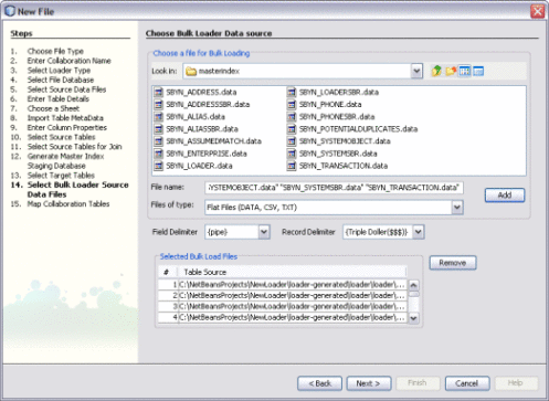
The Choose Bulk Loader Data Source window appears.
-
To specify the source data for the Bulk Loader, do the following:
-
In the upper portion of the window, browse to the location of the of the output files from the Bulk Matcher.
Note –These files are located in NetBeansProjects_Home/Project_Name/loader-generated/loader/work/masterindex, where work is the location you specified for the working directory in loader-config.xml.
-
Select all of the data files in the masterindex directory, and then click Add.
-
-
Click Next.
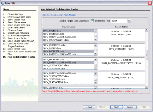
The Map Selected Collaboration Tables window appears.
-
To map source and target data, do the following:
-
To disable constraints on the target tables, select Disable Target Table Constraints.
-
Select the SQL statement type to use for the transfer. You can select insert, update, or both.
-
The wizard automatically maps the source and target tables for you. Review the mapping to verify its accuracy.
Note –Not every table on the left will be mapped. For example, system tables such as SBYN_COMMON_HEADER, SBYN_COMMON_DETAIL, SBYN_APPL, and SBYN_SYSTEMS do not need to be mapped.
-
-
Click Finish.
An ETL collaboration is created for each target table. This might take a few minutes to generate.
Next Steps
You can further configure the ETL collaboration in the ETL Collaboration Editor. For more information, see Configuring ETL Collaborations.
To load the data into the master index database, you can either run each collaboration individually, or you can generate a batch file that will run all collaborations for you. For more information, see Loading Matched Data Using the Data Integrator Wizard Bulk Loader in Loading the Initial Data Set for a Sun Master Index.
ETL Collaboration Overview
Once you have created an ETL collaboration using the Data Integrator Wizard, you can configure and customize the collaboration as needed to meet your data processing requirements. The following topics provide information about ETL collaborations and the ETL Collaboration Editor.
Execution Strategies
Sun Data Integrator automatically employs the most optimum execution strategy for collaborations. The strategy that is employed depends on the specific nature of the collaboration. If you do not want Data Integrator to determine the best execution strategy, you can configure a collaboration for either the staging or the pipeline execution strategy depending on what your Collaboration is set up to do. For example, if your collaboration business logic contains Java operators, you can only use the pipeline strategy. The following describes the criteria that Data Integrator uses to determine the best execution strategy, and these are also the criteria to use when you force an execution strategy.
Execution Strategy Selection
The execution strategy configuration for collaborations is set to the Best Fit option by default. When Data Integrator determines what execution strategy to use for a collaboration, it evaluates the collaboration for specific attributes. For example, it takes tables and columns into consideration. In addition, the selected execution strategy depends on whether a collaboration contains Java operators, which are operators that are not available across all supported databases. Examples of Java operators are date transformation operators and operators that parse business names and addresses and that normalize names. Projects with Java operators must be executed with a pipeline strategy.
You can force the execution strategy for a collaboration by changing its setting from Best Fit to Staging or Pipeline, as described in "Forcing Execution Strategies for Collaborations” .
Data Integrator uses the following execution methods depending on a collaboration's attributes:
Direct/Simple Execution Strategy
With the direct/simple execution strategy, all extraction, transformation, and loading happens in a single database. When the Best Fit option is enabled, Data Integrator uses this strategy under the following conditions:
-
All source tables and target tables reside in the same database.
-
No Java operators are used.
-
The data validation condition is not used.
One Pass Execution Strategy
With one pass execution, extraction and transformation occur in the source database. When the Best Fit option is enabled, Data Integrator uses this strategy under the following conditions:
-
All source tables are in the same database.
-
No Java operators are used.
-
The data validation condition is not used.
Staging Execution Strategy
With the staging execution strategy, all source tables are extracted from source databases and staged in temporary tables in the target database. Join and Transformation happens in the target database. This setting is used automatically when the Best Fit option is enabled and the conditions below occur. You can also select this option manually to force its use, in which case this execution strategy is recommended under the following conditions:
-
Source tables are scattered across different databases.
-
No Java operators are used.
-
The data validation condition is not used.
Pipeline Execution Strategy
With the Pipeline execution strategy, transformation and loading (indirectly to the target database table) occurs in the internal database engine. This setting is used automatically when the Best Fit option is enabled and the conditions below occur. You can also select this option manually to force its use, in which case this execution strategy is recommended under the following conditions:
-
All tables are flat file database tables.
-
Java operators are used.
-
The data validation condition is used.
Whitespace Considerations
Sun Data Integrator handles whitespace differently depending on the execution strategy. When joining a flat file table and an Oracle table where the comparison column in the Oracle table contains whitespace, refer to the table below.
Table 1–1 Execution Strategies for Flat File and Oracle Table Joins|
Strategy Specified |
Description |
|---|---|
|
Best Fit |
Uses the staging execution strategy since the source tables are from different databases. The results will be the same as if staging was selected. |
|
Staging |
Data Integrator extracts source tables from source databases and stages the data in temporary tables in the target database. By default, whitespace is trimmed. |
|
Pipeline |
Data Integrator uses an internal database engine instead of temporary tables, accessing data directly from the source tables rather than extracting it to temporary tables. To avoid whitespace causing failure in the join condition, add LTRIM/RTRIM operators to the Oracle table column. The result will be the same as Staging/Best Fit. Note – In future this feature will be made obsolete |
Explicit and Implicit Joins
The join condition specified on source tables is an explicit join. The condition specified on target tables is an implicit join. The target condition is used differently in insert and update statements. For update statements, the condition from the target table is used to identify the proper rules to update and match the rules to the target. For insert statements, the condition from the target table is used to verify that no duplicate rules are inserted.
Runtime Properties
The Staging Table Name property is used for the staging execution strategy. When you use the staging strategy and specify a staging table name for each target table, the ETL collaboration does not create a temporary staging table for the source data. Instead the table in the default table space for the target database with the name specified for this property is used for staging.
When all the source tables in an ETL collaboration are configured with a valid table name in the Staging Table Name property, the ETL process does not create or delete any temporary tables at runtime. Also, the process does not modify or alter the target tables other than for updating records as per the ETL collaboration.
Be careful about changing the default settings. By default, the staging table are dropped after each run. If you do not want to drop the tables, you need to change the Drop Staging Table property to false. Also by default, the data in a temporary table is truncated before each run. If you do not want the table truncated, set the Drop Staging Table property to false.
Data Validation Conditions
Data Integrator provides operators to validate extracted data. You can validate multiple columns in a record through Data Validation Conditions. If the validation fails for at least one of the columns then the record is rejected, preventing it from being loaded into target tables. All windows that show conditions (for example, the Data Validation Condition window and the Extraction Condition window) provide the operators to enable you to model complex validation conditions. You can view rejected rows at design time. If a data validation condition is set, click Run Collaboration to see if any records fail validation. If rejected rows exist, right-click the target table and select Show Rejected Data. The rejected data displays in the Output pane.
About the ETL Collaboration Editor
You use the ETL Collaboration Editor to create the business logic for ETL processes. The table below describes the ETL Collaboration Editor toolbar.
Table 1–2 ETL Collaboration Editor Toolbar
Configuring ETL Collaborations
Once you create an ETL collaboration using the Data Integrator Wizard, you can modify the collaboration to customize the processing logic. The ETL Collaboration Editor provides a variety of tools, commands, and operators to configure the ETL process.
Perform any of the following tasks to configure your ETL collaborations:
Joining Source Tables
Data Integrator allows you to join data from multiple sources before extraction. You can create join views by creating a join condition that joins source tables.
Note –
For optimal performance, join the most unique columns in the first join and the least unique columns in a second join.
 To Join Source Tables
-
Open the ETL collaboration in the ETL Collaboration Editor.
-
In the ETL Collaboration Editor toolbar, click Create New Join.
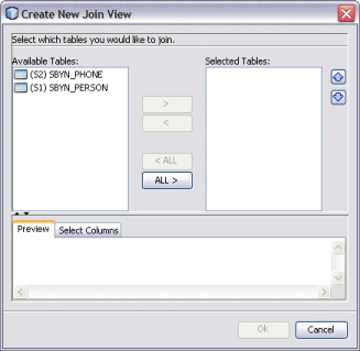
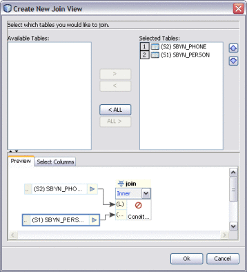
The Create New Join View dialog box appears.
-
Under Available Tables, select the tables you want to join and then click the right arrow.
The tables move to the Selected Tables column, and the join is represented graphically in the Preview panel.
-
In the Preview panel, click the down arrow in the join condition and select the type of join to use from the following options.
-
Inner – Use this if all tables to be joined contain the same column.
-
Left Outer – Use this if the results should always include the records from the left table in the join clause.
-
Right Outer – Use this if the results should always include the records from the right table in the join clause.
-
Full Outer – Use this if the results should always include the records from both the right and left tables in the join clause.
-
-
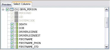
By default, all columns are selected for the join condition. To deselect any columns, click the Select Columns tab and then deselect any columns you do not want to include in the join.
-
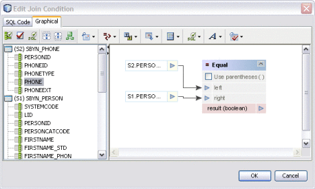
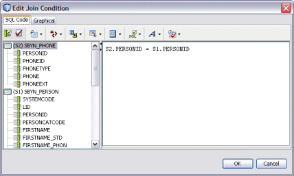
To define the join condition, click inside the join box. On the Edit Join Condition dialog box, do the following:
-
To view the SQL code while you create the join condition, click the SQL Code tab. To view the join condition graphically, click the Graphical tab.
-
Define the join condition by dragging column names from the list in the left panel. Join the column names by dragging operators from the toolbar.
In the example below (shown in both source code and graphical views), PERSONID was dragged from the SBYN_PHONE table first. Then the equals operator, located in the Comparison Operators menu, was dragged next to PERSONID. To complete the condition, PERSONID was dragged from the SBYN_PERSON table.
-
Define as many conditions as needed.
-
When you are done defining conditions, click OK.
-
-
Click OK on the Edit Join View dialog box.
 To Join Source Tables During Mapping
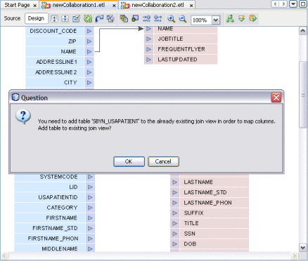
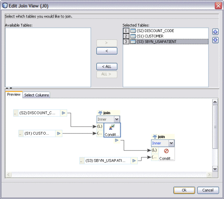
If two source tables are already joined and have columns that are mapped to a target table, you can add another source table to the join by mapping a column in that table to the target table. For example, if source tables S1 and S2 are joined and mapped to target table T1, you can add source table S3 to the join by mapping a column from S3 to T1.
-
Map a columns from the source target you want to add to the join to the target table that is already mapped to the joined tables.
A dialog box appears asking whether you want to add the new table to the join.
-
Click OK to add the new source table to the existing join view.
The Edit Join View dialog box appears.
-
Click in the second join box in the Preview panel.
-
Define the join conditions by dragging columns and operators onto the canvas.
Modifying an Existing Join
Once you create a join between source tables, you can modify the join condition if needed.
Note –
For optimal performance, join the most unique columns in the first join and the least unique columns in a second join.
 To Join Source Tables
-
Open the ETL collaboration in the ETL Collaboration Editor.
-
In the ETL Collaboration Editor canvas, right-click the join view and select Edit Join View.
The Create New Join View dialog box appears.

-
Do any of the following:
-
Under Available Tables, select additional tables you want to join and then click the right arrow.
The tables move to the Selected Tables column, and the join is represented graphically in the Preview panel.

-
In the Preview panel, click the down arrow in the join condition and select the type of join to use from the following options.
-
Inner – Use this if all tables to be joined contain the same column.
-
Left Outer – Use this if the results should always include the records from the left table in the join clause.
-
Right Outer – Use this if the results should always include the records from the right table in the join clause.
-
Full Outer – Use this if the results should always include the records from both the right and left tables in the join clause.
-
-
To modify the columns included in the join condition, click the Select Columns tab and then select or deselect any columns.

-
To define the join conditions, click inside the join box. On the Edit Join Condition dialog box, define the join conditions by dragging column names from the list in the left panel. Join the column names by dragging operators from the toolbar.
Note –You can perform this step viewing either the source code or a graphical representation of the source code. For information about available operators, see . The figure below shows a simple example of a join condition.

-
Defining Extraction Conditions and Validations
You can set up collaborations to filter data from source tables using extraction conditions and validations. When the collaboration runs, it will only extract data based on the conditions and validations you define.
 To Define Extraction Conditions and Validation.
-
Open the collaboration you want to edit.
-
Right-click the source table and click Properties.
The Properties panel appears. By default, the extraction type is configured for conditional extraction. To leave the source data unfiltered, set the Extraction Type property to Full Extraction.
-
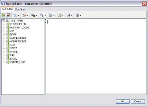
To define extraction conditions, click the ellipsis button next to the Extraction Condition property.
The Extraction Condition dialog box appears.
-
Define the condition by dragging columns and operators onto the canvas, and then click OK.
-
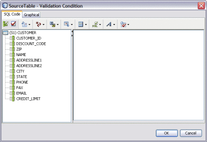
To define validations for extraction, click the ellipsis next to the Validation Condition property.
The Validation Condition dialog box appears.
-
Define the condition by dragging columns and operators onto the canvas, and then click OK.
-
To specify that only unique records be extracted, select the check box next to Select Distinct. To extract all records regardless of duplication, deselect Select Distinct.
Adding Tables to an Existing Collaboration
Once you have defined source and target tables using the Data Integrator Wizard, you can add additional tables as needed. Adding tables is a simple drag and drop procedure.
 To Add Tables to a Collaboration
-
Open the ETL collaboration you want to edit.
-
On the Services window, expand Databases.
-
Right-click the database containing the tables you want to add to the collaboration, and then click Connect.
-
Expand the Tables node under the database you just connected to.
-
Select a table and drag it onto the ETL Collaboration Editor canvas.
-
On the dialog box that appears, select either Source Table or Target Table.
-
If you selected Source Table, do one of the following on the Confirm Join Creation dialog box:
-
To add the new table without creating a join to an existing table, click No.
-
To create a join between the new table and an existing table, click Yes. The Create New Join View dialog box appears. Define the join as described in Joining Source Tables.
-
Forcing Execution Strategies for Collaborations
The procedure below describes how to force an execution strategy for ETL Collaborations. If you are using Java operators, you must select the Pipeline option. For more information about execution strategies, see Execution Strategies.
 To Force Execution Strategies for Collaborations
-
Open the ETL collaboration you want to edit.
-
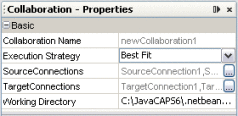
Right-click the ETL Collaboration Editor window and click Properties.
The Properties panel appears in the right side of the window.
-
In the Execution Strategy property, select Pipeline or Staging.
Changing the Database URL for Design Time
For database ETL collaborations, the design-time test run uses the same URL, catalog, or schema name to connect to the database table as when the collaboration was created.
You can change the database URL to point to a different location or even a different table name as long as the content structure is the same. Restarting the NetBeans IDE reverts the URL back to its original value.
Note –
To change DB2 catalog and schema names, modify the table properties by adding user-defined information in the Expert tab.
 To Change the Database URL for Design Time
-
Open the collaboration you want to edit.
-
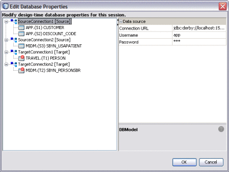
Right-click the ETL Collaboration Editor window and click Database Properties.
The Edit Database Properties dialog box appears as shown below.
-
In the left panel, select the database whose URL you want to change.
-
Enter a new URL for the database to connect to during design time.
-
Enter or verify the user name and password.
-
Click OK.
Configuring Source Table Properties
You can customize the ETL process by defining certain properties for the source tables. Several properties cannot be changed once they have been set. Changes in the Properties sheet are saved with the ETL collaboration.
Note –
To change DB2 catalog and schema names, modify the table properties by adding user-defined information in the Expert tab.
 To Configure Source Table Properties
-
Open the collaboration you want to edit.
-
Right-click the source table you want to configure, and then click Properties.
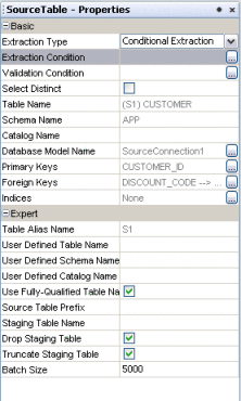
The Source Table – Properties panel appears.
-
Modify any of the editable properties described in the table below.
Property
Description
Extraction Type
The type of data extraction to perform for the table. Select Conditional Extraction if you will define conditions. Select Full Extraction to extract all data.
Extraction Condition
The extraction condition defined for the source table. You can create or edit a extraction condition by clicking the ellipsis button to the right of the property.
Validation Condition
The validation condition defined for the source table. You can create or edit a validation condition by clicking the ellipsis button to the right of the property.
Select Distinct
An indicator of whether to only select unique records from the source table or to select all records regardless of duplication.
Table Name
The name of the source table.
Schema Name
The name of the database schema that contains the source table.
Catalog Name
The name of the database catalog containing the schema being used.
Database Model Name
A name given by Data Integrator to each source table.
Primary Keys
Any primary key columns contained in the table.
Foreign Keys
Any foreign key columns contained in the table.
Table Alias Name
The alias given to the table for identification in SQL statements.
User Defined Table Name
A table name to be used during design time.
User Defined Schema Name
A schema name to be used during design time.
User Defined Catalog Name
A catalog name to be used during design time.
Use Fully-Qualified Table Name
An indicator of whether to use the fully qualified name for the table.
Source Table Prefix
A prefix to use for the source table.
Staging Table Name
The name of the table to use in the internal staging database. Data Integrator also supports dynamic staging table names. The staging table name can be generated in a business process and passed to the collaboration. The staging tables names must be unique.
Drop Staging Table
An indicator of whether to drop the internal staging table each time the collaboration is run.
Truncate Before Load
An indicator of whether to truncate the internal staging table each time the collaboration is run.
Batch Size
The number of records to extract for each batch.
Configuring Target Table Properties
You can customize the ETL process by defining certain properties for the target tables. Several properties cannot be changed once they have been set. Changes in the Properties sheet are saved with the ETL Collaboration.
Note –
To change DB2 catalog and schema names, modify the table properties by adding user-defined information in the Expert tab.
 To Configure Target Table Properties
-
Open the collaboration you want to edit.
-
Right-click the target table you want to configure, and then click Properties.
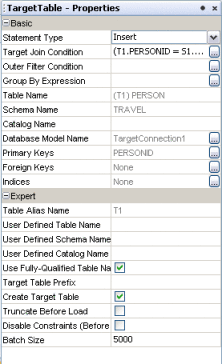
The Target Table – Properties panel appears.
-
Modify any of the editable properties described in the table below.
Using Pre-Created Temporary Staging Tables
You can manage temporary tables by configuring source table properties. When all the source tables in an ETL collaboration are configured with a valid table name for the Staging Table Name property, no create or drop privileges are required for the target environment.
 Using Temporary Staging Tables
-
Open the collaboration you want to edit.
-
Right–click a source table, and select Properties.
-
Enter a valid table name for the Staging Table Name property.
Ensure that the source and staging table structures are the same, including column names and data types. If the staging table structure does not match the corresponding source table, the collaboration will fail with an error message.
-
Select or deselect the Drop Staging Table property to specify whether or not to drop the temporary staging table after the ETL process completes.
-
Select or deselect the Truncate Staging Table property to specify whether or not to truncate the temporary staging table before each run.
Viewing Table or Join Data
On the ETL Collaboration Editor, you can view data contained in source and target tables. You can also view the output data from a join.
 To View Table or Join Data
-
Open the collaboration you want to view.
-
To view the data, do one of the following:
-
To view a table's data, right-click on the table and then select Show Data.
-
To view the output data for a join, right-click the join view header and then select Show Data.
The contents of the selected table or the output data for the join appears in the Data Integrator Output panel.
-
Viewing the SQL Code
You can view SQL code generated for each table and operator in the ETL collaboration canvas.
 To View SQL Code
-
Open the ETL collaboration you want to view.
-
Right-click the table or operator on the canvas and click Show SQL.
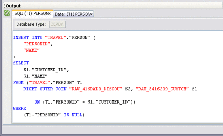
The Output section in the lower panel of the NetBeans window displays the generated SQL code, as shown in the following figure.
Viewing Runtime Output Arguments
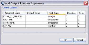
Sun Data Integrator provides a constant list of output arguments for all ETL collaborations. Runtime outputs can be captured and displayed or written to a file. These messages are made available automatically by the system.
Runtime output arguments include the following:
-
Count – Shows the row count for the Insert, Update, or Delete statement.
-
Status – Shows whether the Insert, Update, or Delete operation was successful or if it failed.
-
Starttime: Shows the start time of the runtime ETL process.
-
Endtime: Shows the end time of the ETL process.
 To View Runtime Output Arguments
-
Open the collaboration you want to view.
-
Right-click in the ETL Collaboration Editor, and select Runtime Outputs.
The Add Output Runtime Arguments dialog box appears.
Fine-Tuning the ETL Process
ETL collaborations can extract data without filtering or with filtering using runtime inputs. You can also configure the batch size and configure the collaboration to use the same source table multiple time. Perform any of the following steps to configure the data extraction.
Filtering Source Data Using Runtime Inputs
Sun Data Integrator allows you to pass values, known as runtime inputs, to ETL collaborations at runtime. You can use these values in extraction conditions. However, the use of such dynamic values are not limited to extraction; you can also pass values from BPEL business processes.
The following procedure describes how to add input runtime arguments to a Collaboration.
 To Filter Source Data Using Runtime Inputs
-
Open the collaboration you want to edit.
-
Right-click the ETL Collaboration Editor window and select Runtime Inputs.
The Add Input Runtime Arguments dialog box appears.
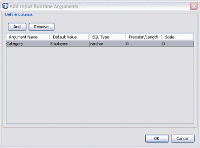
-
Click Add.
An empty row appears.
-
Double-click the empty row under Argument Name and enter the name for source record to be filtered.
-
Press Tab and enter the content that the record must contain to be selected.
-
Press Tab and select the SQL type for the record.
-
Press Tab and enter a number indicating the maximum length of the record.
-
Press Tab and enter a number indicating the scale for the record.
-
Click OK.
Setting the Batch Size for Joined Tables
To increase performance during collaboration execution, you can configure the batch size for the temporary tables created for joined source tables. By tuning the batch size you can load data more efficiently into source tables.
By default, 5000 rows are populated at the same time into a source table. There is no upper limit to the batch size. The limit is determined by the amount of internal memory available on the machine running the collaboration. Generally, the lower the number the better, but adjust the value to determine the optimum performance.
Note –
The source table batch size only affects temporary source tables. To limit the number of rows fetched at a time, specify the batch size in the Properties panel for the target table.
 To Set the Batch Size for Joined Tables
-
Open the collaboration you want to edit.
-
Right-click the source table to set the batch size for, and then select Properties.
The Properties panel appears.

-
In the Batch Size property (under the Expert heading), enter the number of rows to populate at the same time into the temporary source table.
-
Click OK.
Using Table Aliases with Multiple Source Table Views
Sun Data Integrator only allows you to map a column in a source table to one column in a target table. If you need to map one source column to multiple target columns, you can use multiple instances of the same source table with different aliases. This topic gives a scenario and example for doing this.
The project has the following source tables: EMP_TBL and CODES_TBL. You can create a join view with these tables and you can drag another view of the CODES_TBL to the ETL Collaboration Editor canvas to create a third join. The third join is used in a code lookup.
The following table displays the sample data for the EMP_TBL source table:
Table 1–3 Employee Table|
NAME |
ID |
JOB CODE |
DEPT CODE |
|
Dave |
1 |
p |
D1 |
|
Judy |
2 |
c |
D2 |
The following table displays the sample data for the CODES_TBL source table:
Table 1–4 Company Codes|
CODE |
VALUE |
|
D1 |
Human Resource |
|
D2 |
Marketing |
|
P |
Permanent |
|
C |
Contractor |
The following figure shows the Collaboration and mapping with the correct data from a test run. The lookup loads the description for both jobs and departments from the CODES_TBL table. In this example, the table CODES_TBL is used twice in the join condition with aliases S2 and S3. In the join condition S2.Code is joined with S1.JOB_CODE and S3.Code is joined with S1.DEPT_CODE.
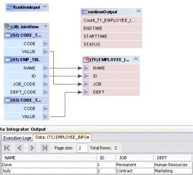
As you can see in the following figure, the first join view shows the condition S1.JOB_CODE = S2.CODE. This will load the job descriptions from the CODES_TBL to the target table column JOB.
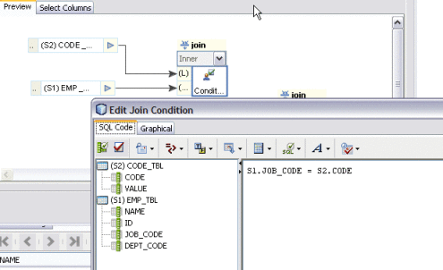
The following figure shows the second join view with the condition S1.DEPT_CODE = S3.CODE. This loads the department descriptions from the CODES_TBL to the target table column DEPT.
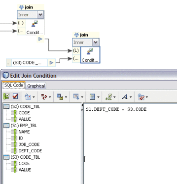
Grouping Input Data
Sun Data Integrator supports extracting aggregated data, applying special transformations, and loading them to a target table. Specific transformations are supported for aggregated values such as Minimum, Maximum, Count, Sum, and Average. You can aggregate column(s) based on a selection specified using the Group By Expression option. This option can only be used with Insert/Update statements.
 To Group Input Data
-
Open the collaboration you want to edit.
-
In the ETL Collaboration Editor, right-click the target table and click Properties.
The Properties panel appears.
-
Click the ellipsis button next to the Group By Expression property.
The Group By Expression dialog box appears.
Note –The Group By Expression option does not affect Upsert or Delete statements.
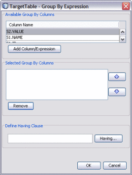
-
Select a column to add to the group by expression, and then click Add Column/Expression.
-
To add a HAVING clause, click Having.
The Having Condition window appears.
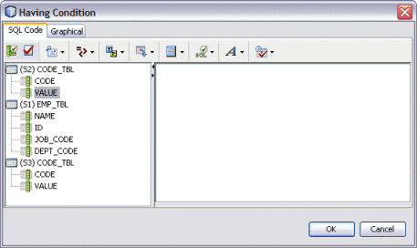
-
Define the expression that a column must include to be grouped and click OK.
-
Click OK on the Group By Expression dialog box.
Viewing and Modifying Table Data
You can view the data contained in any of the source or target tables included in an ETL collaboration. You can also perform some data modification, such as inserting and deleting rows, truncating the table, and copying table data.
 To View and Modify Table Data
-
Open the collaboration you want to view or edit.
-
Right-click the table in the ETL Collaboration Editor, and select Show Data.
-
To add a record, do the following:
-
To delete a record, do the following:
-
To copy table data to the clipboard, do the following:
-
In the Data Integrator Output panel, select the data to copy.
You can select one or more cells or rows.
-
Right-click on the cell or row and select one of the following options:
-
Copy Cell Value to copy just the selected cell.
-
Copy Row Values to copy the entire row.
-
Copy Row Values With Header to copy the entire row along with the corresponding column or header names.
-
-
Paste the information to the desired location, such as a word processing application.
-
-
To truncate the displayed table, click Truncate This Table in the left toolbar of the Data Integrator Output panel.
- © 2010, Oracle Corporation and/or its affiliates

