| Skip Navigation Links | |
| Exit Print View | |

|
Oracle ZFS Storage ZS3-ES Installation Guide |
About the Installation Procedure
Installation Procedure Overview
About Server Features and Components
Front Panel Status Indicators, Connectors, and Drives
Back Panel Status Indicators, Connectors, and PCIe Slots
Preparing for Server Installation
Tools and Equipment Needed for Installation
Installing the Server Into a Rack
Safety Precautions When Rackmounting the Server
Stabilize the Rack for Installation
Attach Tool-less Slide-Rail Assemblies
Install the Server Into the Slide-Rail Assemblies
Install the Cable Management Arm
Remove the Cable Management Arm
Verify Operation of Slide-Rails and CMA
Rear Cable Connections and Ports
Connect Data Cables to the Server
Connect to Oracle DE2 Disk Shelves
Powering On and Initially Configuring the Server
Power on the Oracle Disk Shelves and Servers
Configure the Primary Network Interface
Troubleshooting Installation Issues
Oracle ILOM Hardware and Interfaces
Logging In to Oracle ILOM Using a Local Serial Connection
Logging In to Oracle ILOM Using a Remote Ethernet Connection
Troubleshooting the Service Processor Connection
Resetting the Service Processor Using Oracle ILOM
Reset the Service Processor From the Server Back Panel
Emergency Server Power Down Using the Power Button
Emergency Server Power Down Using the Oracle ILOM CLI
Emergency Server Power Down Using the Oracle ILOM Web Interface
Use the Oracle ILOM Command-Line Interface to Reset the Server
Use the Oracle ILOM Web Interface to Reset the Server
Technical Support Information Worksheet
Locating the System Serial Number
Getting Server Firmware and Software
Firmware and Software Access Options
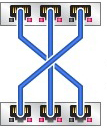
This section describes how to attach the three cluster cables to connect the two servers together for communication. These cables connect two serial links (outer connectors) and one Ethernet link (middle connector).
To locate PCIe card slot 2, see Back Panel Status Indicators, Connectors, and PCIe Slots.
These are straight-through Cat-5-or-better Ethernet cables, and are typically 1m in length.
Figure 25 Connecting the Cluster Cables
