Selecting the Correct Processor Removal and Replacement Tool
 | Caution - The correct color-coded processor removal and replacement tool must be used to remove and replace a processor; otherwise, the processor or the processor socket might be damaged. Additionally, do not use a tool that is designed for earlier generations of Intel processors (CPUs). If you use an earlier generation tool, the processor will only be partially held by the tool and it could fall from the tool, which could damage the processor socket. |
Selecting the correct processor removal and replacement tool is a two-step process. First you determine the size of the processor that is being replaced, then you select the removal and replacement tool that fits that size.
The processors supported by the Oracle Server X5-2 come in two sizes. The processors with 10 or fewer cores are smaller than the processors with 12 or more cores. You can determined the size of the processor that you are going to remove and replace in either of two ways:
-
Use Oracle Integrated Lights Out Manager (ILOM) 3.2 to display processor information.
For instructions, refer to the Oracle Integrated Lights Out Manager (ILOM) 3.2 Documentation Library at http://www.oracle.com/goto/ILOM/docs.
-
Or
-
Visually check the size of the processor installed in the server.
This requires that you remove the processor heatsink and open the independent loading mechanism (ILM) assembly that holds the processor in the socket. For instructions, see Remove a Processor. This is the same procedure that you will use when you remove the processor.
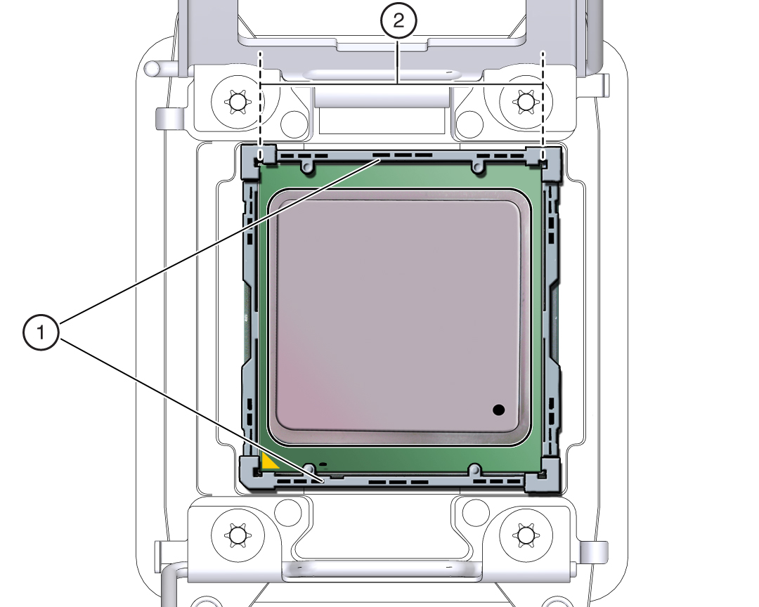
If you choose to visually check the size of the processor, refer to the next two figures to see how to distinguish the smaller processors from the larger processors. Figure 7 shows a smaller processor installed. Notice that the right and left edges of the processor are within the boundaries of the processor alignment brackets.
Figure 7 Smaller Processor Installed in a Motherboard Processor Socket

|
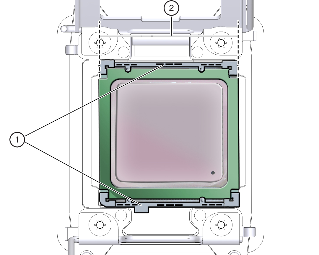
Figure 8 shows a larger processor installed. Notice that the right and left edges of the processor extend beyond the boundaries of the processor alignment brackets.
Figure 8 Larger Processor Installed in a Motherboard Processor Socket

|
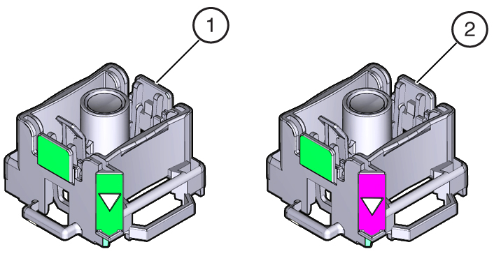
After you have determined the size of the processor installed in your server, select the correct processor removal and replacement tool. Like the processors, the processor removal and replacement tool also comes in two sizes. The tool for the smaller processors (processors with 10 or fewer cores) is color-coded green. The tool for the larger processors (12 or more cores) is color-coded pink. See Figure 9.
Figure 9 Color-Coded Processor Removal and Replacement Tools

|
 | Caution - The pink color-coded processor removal and replacement tool must be used only with the larger processors (12 cores or more). Likewise, the green color-coded removal and replacement tool must be used only with smaller processors (10 cores or less); otherwise, the processor or the processor socket might be damaged. |
The following table provides an easy reference for matching a processor (by number of cores or model number) to the correct processor removal and replacement tool. The processor removal and replacement tool part number is also recorded on the tool.
|
Note - The correct processor removal and replacement tool is included in the box with the replacement processor. Additionally, both removal and replacement tools ship with replacement motherboards.