Interpreting LEDs
Use these steps to determine if an LED indicates that a component has failed in
the server.
|
|
|
|
1.
|
Check the LEDs on the front and rear of the server.
|
|
|
2.
|
Check the LEDs on the individual components.
Note -
Component LEDs might not be lit even though the component
is faulty. Use the instructions in these links to determine
if the component has been diagnosed as being faulty.
|
|
|
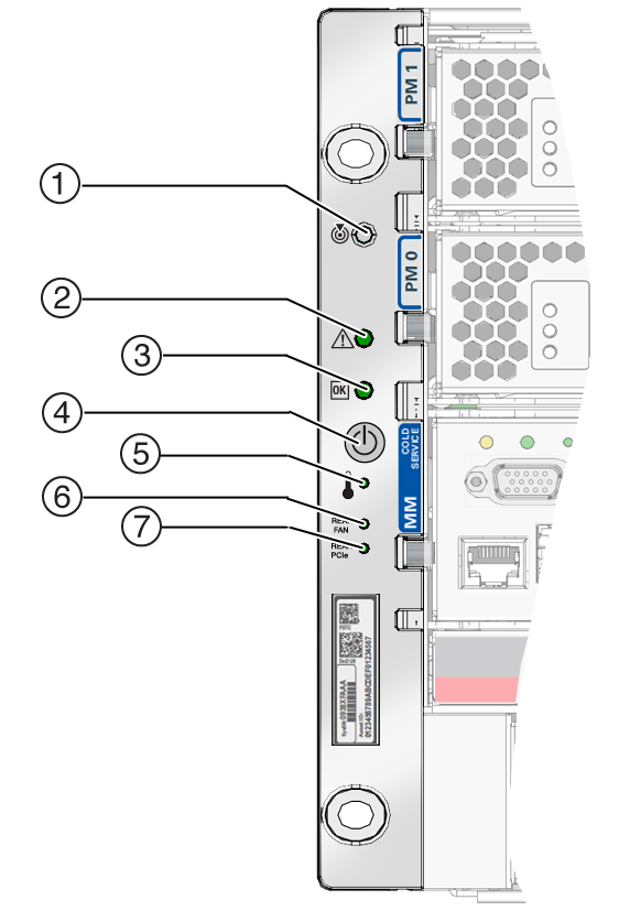
Front Panel Controls and LEDs

|
|
|
|
|
1
|
Locator LED and button (white)
|
|
You can turn on the Locator LED to identify a particular
server. When lit, the LED blinks rapidly. Turn on the
Locator LED by pressing the Locator button, or see Locate the Server. |
|
2
|
Server Service Required LED (amber)
|
|
The fmadm
faulty command provides details about any
faults that cause this indicator to light. See Check for Faults. Under some fault conditions, individual component fault
LEDs are lit in addition to the Server Service Required
LED.
|
|
3
|
Power OK LED (green)
|
|
Indicates these conditions:
-
Off –
Server is not running in its normal state. Server
power might be off. The SPM might be running.
-
Steady on
– Server is powered on and is running in its
normal operating state. No service actions are
required.
-
Fast blink
– Server is running in standby mode and can be
quickly returned to full function.
-
Slow blink
– A normal but transitory activity is taking
place. Slow blinking might indicate that server
diagnostics are running or that the server is
booting.
|
|
4
|
Power button
|
|
|
|
5
|
System Overtemp LED(amber)
|
|
Indicates these conditions:
-
Off –
Indicates a steady state, no service action is
required.
-
Steady on
– Indicates that a temperature failure event
has been acknowledged and a service action is
required.
|
|
6
|
Fan Module Fault LED(amber)
|
Rear FM
|
Indicates these conditions:
-
Off –
Indicates a steady state, no service action is
required.
-
Steady on
– Indicates that a fan module failure event
has been acknowledged and a service action is
required on at least one of the fan modules.
|
|
7
|
PCIe Card Fault LED(amber)
|
Rear PCIe
|
Indicates these conditions:
-
Off –
Indicates a steady state, no service action is
required.
-
Steady on
– Indicates that a failure event has been
acknowledged and a service action is required on at
least one of the PCIe cards.
|
|
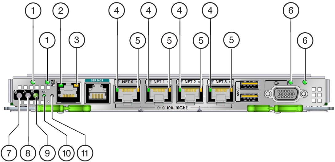
Rear Panel Controls and LEDs

|
|
|
|
|
1
|
AC 0 (left) and AC 1 (right) power LED
|
|
Indicates these conditions:
|
|
2
|
Net MGT port link LED
|
|
Indicates these conditions:
|
|
3
|
Net MGT port speed LED
|
|
Indicates these conditions:
|
|
4
|
Network port link LED
|
|
Indicates these conditions:
|
|
5
|
Network port speed LED
|
|
Indicates these conditions:
-
Off – The
link is operating as a 10-Mbps connection or there
is no link.
-
Amber on
– The link is operating as a 100-Mbps
connection.
-
Green on
– The link is operating as a Gigabit
connection (1000 Mbps).
|
|
6
|
AC 2 (left) and AC 3 (right) power LEDs
|
|
Indicates these conditions:
|
|
7
|
Locator LED and button (white)
|

|
Turn on the Locator LED by pressing the Locator button, or
see Locate the Server. When lit, the LED blinks
rapidly. |
|
8
|
Server Service Required LED (amber)
|

|
The fmadm
faulty command provides details about any
faults that cause this indicator to light. See Check for Faults. Under some fault conditions, individual component fault
LEDs are lit in addition to the Service Required LED.
|
|
9
|
Power OK LED (green)
|

|
Indicates these conditions:
-
Off –
Server is not running in its normal state. System
power might be off. The SPM might be running.
-
Steady on
– Server is powered on and is running in its
normal operating state. No service actions are
required.
-
Fast blink
– Server is running in standby mode and can be
quickly returned to full function.
-
Slow blink
– A normal but transitory activity is taking
place. Slow blinking might indicate that system
diagnostics are running or that the system is
booting.
|
|
10
|
SP LED
|
SP
|
Indicates these conditions:
-
Off – AC
power might have been connected to the power
supplies.
-
Steady on,
green – SPM is running in its
normal operating state. No service actions are
required.
-
Blink, green
– SPM is initializing the Oracle ILOM
firmware.
-
Steady on,
amber – An SPM error has occurred
and service is required.
|
|
11
|
Overtemp LED(amber)
|

|
Indicates these conditions:
-
Off –
Indicates a steady state, no service action is
required.
-
Steady on
– Indicates that a temperature failure event
has been acknowledged and a service action is
required.
|
|

