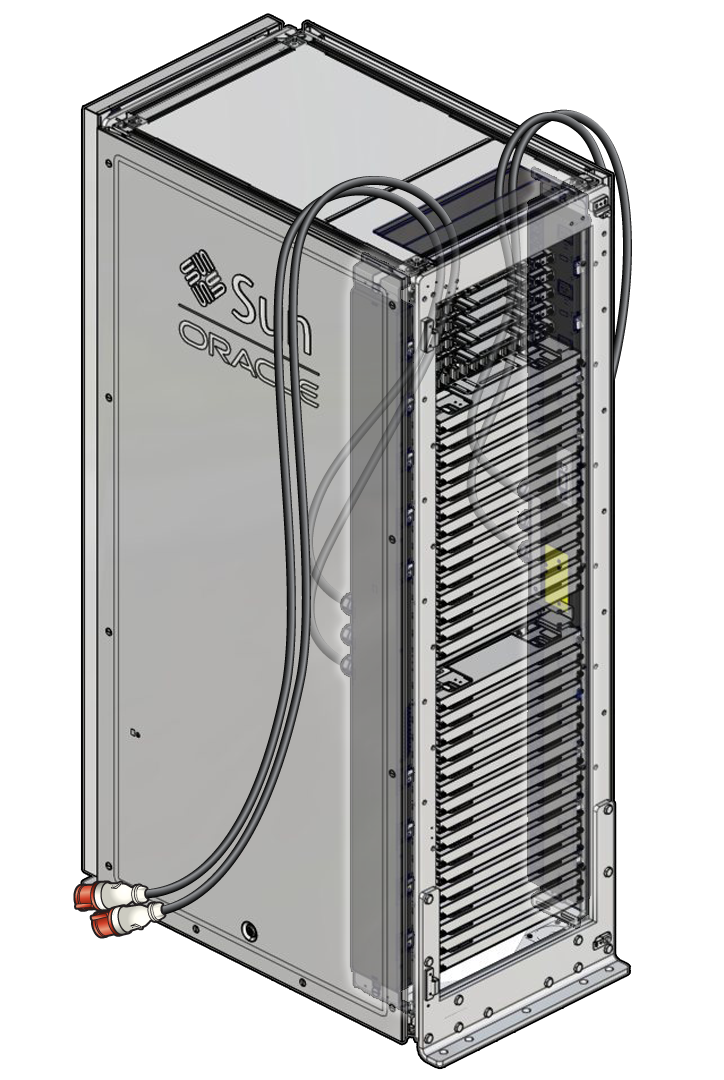
Provide Access to a PDU
If the modular system is installed in a location where enough physical access to the side panel and PDUs are not possible, for example, if multiple systems are side-by side, you must move the modular system that contains the faulty PDU.
Note - If the modular system is mounted to the floor with concrete anchor bolts, you will need an M12 torque wrench and 10 new M12 concrete anchors and bolts, such as Hilte HSL-3-B M12/25, to reanchor the modular system.
-
Remove the front and rear doors of the modular system cabinet.

-
If access to the modular system requires moving it, perform the
following steps:
-
Follow safety precautions.
See Safety Notices.
- Disconnect the I/O cables from the modular system.
- Disconnect the power cords to the other PDU.
- If the modular system is mounted to the floor, use an M12 torque wrench to remove the anchor bolts, and discard the used anchor bolts.
- Remove the seismic brackets.
- If the system has castor rollers, unlock them.
-
Using two persons, carefully move the modular system to a
nearby location that allows space for removing the side panel and
performing the PDU replacement.
Move the Modular System to the Installation Location in Netra Modular System Installation Guide

Caution - The side panel's grounding strap is not visible until the side panel is partially removed. Be careful not to damage the grounding strap when removing the side panel.
-
Follow safety precautions.
- Remove the side panel and disconnect the grounding strap corresponding to the PDU that is being replaced.
-
Remove the seismic side:
- Remove any straps holding cables to the seismic side.
- Disconnect the ground strap to the seismic side.
-
Using a T-30 Torx screwdriver, remove and set aside the 24 screws that connect the seismic side to the RETMA rail top hats.

Caution - In the next step, remove the top 4 screws last, and support the seismic side as you remove these last 4 screws.
- Using a T-30 Torx screwdriver, remove and set aside the 30 screws that connect the seismic side to the frame.
-
Remove the four screws holding the coupler panel to its support brackets, then carefully pull the coupler panel out of the way.
Note - Do not disconnect any cables from the coupler panel. - Remove the following:
-
Remove the faulty PDU.
See Remove a PDU.