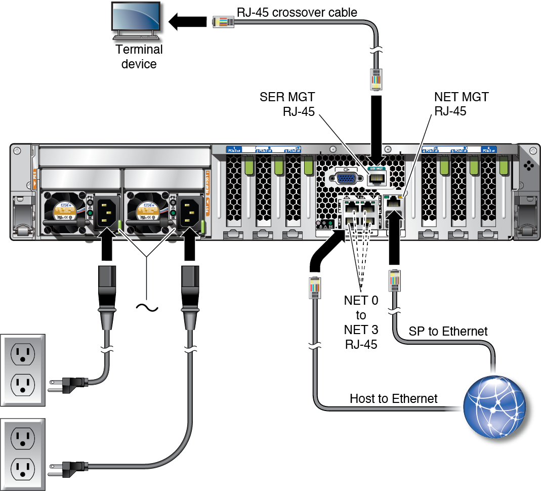
Connect Cables
-
Connect a Category 5 (or better) RJ-45 cable from the SER MGT port to a
terminal device.

Caution - Do not attach a modem to this port.
The SP serial management port is labeled SER MGT. Use the SER MGT port only for server management. This port is the default connection between the SP and a terminal or a computer.
When connecting a DB-9 cable, use an adapter to perform the crossovers given for each connector.
-
Configure a terminal or terminal emulator with these settings:
-
9600 baud
-
8 bits
-
No parity
-
1 Stop bit
-
No handshake
A null modem configuration is needed, meaning the transmit and receive signals are reversed (crossed over) for DTE to DTE communications. You can use the supplied RJ-45 crossover adapters with a standard RJ-45 cable to achieve the null modem configuration.
Note - If you power on the server for the first time and do not have a terminal or terminal emulator (PC or workstation) connected to the SP SER MGT port, you will not see system messages. -

-
Configure a terminal or terminal emulator with these settings:
-
Connect a Category 5 (or better) RJ-45 cable from the NET MGT port to your
network switch or hub.
The SP network management port is labeled NET MGT. After the initial server configuration, you can connect to the SP over an Ethernet network using this NET MGT port.
If your network uses a DHCP server to assign IP addresses, the DHCP server assigns an IP address to this NET MGT port. With this IP address, you can connect to the SP using an SSH connection. If your network does not use DHCP, this NET MGT port is not accessible until you configure the network settings through the SER MGT port. For instructions, see Assign a Static IP Address to the NET MGT Port.
-
Connect Category 5 (or better) cables from your network switch or hub to the
remaining Ethernet ports (NET 0, NET 1, NET 2, NET 3) on the rear of the
chassis, as needed.
The server has four Gigabit Ethernet network connectors, marked NET 0, NET 1, NET 2, and NET 3. Use these ports to connect the server to the network. The Ethernet interfaces operate at 100 Mbps, 1000 Mbps, and 10000 Mbps. See, Identifying Ports.
Note - The Oracle ILOM sideband management feature enables you to access the SP using one of these Ethernet ports. Refer to the section Sideband Network Management Connection in the Oracle ILOM Administrator's Guide for Configuration and Maintenance.
Note - To achieve 1GbE network speeds, use Category 6 (or better) cables and network devices that support 1000BASE-T networks. -
If your server configuration includes optional PCIe cards, connect the
appropriate I/O cables to their connectors.
Refer to the PCIe card documentation for specific instructions.
-
Route the power cords from separate AC power sources to the server, then
connect the power cords to the power supplies.
When the power cords are connected, the SP initializes and the power supply LEDs illuminate. After a few minutes, the SP login prompt is displayed on the terminal device. At this time, the host is not initialized or powered on.

Caution - Do not attach power cables to the power supplies until you have connected the server to a serial terminal or a terminal emulator (PC or workstation). The server goes into Standby mode as soon as a power cable connects a power supply to an external power source. System messages might be lost after 60 seconds if a terminal or terminal emulator is not connected to the SER MGT port before power is applied.
Note - Oracle ILOM signals a fault if both power supplies are not cabled at the same time, since it will be a nonredundant condition. Do not be concerned with this fault in this situation.