Identifying Ports
This topic provide the pin descriptions of the ports.
USB Ports
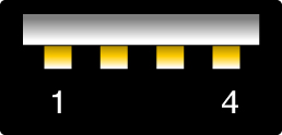
Two USB 3.0 ports can be accessed from the rear of the server and two USB 2.0 ports from the front. See the location of the USB ports at Front Panel Components and Rear Panel Components. The USB ports support hot-plugging. You can connect and disconnect USB cables and peripheral devices while the server is running, without affecting server operations.
Each USB 2.0 port supplies 5V output at 500 mA.
Each USB 3.0 port supplies 5V output at 900 mA.
Note - You can connect up to 126 devices to each of the four USB controllers (two ports in front, two ports in the rear), for a total of 504 USB devices per server.

|
SER MGT Port
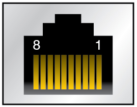
The SER MGT RJ-45 port, located on the rear panel, provides a TIA/EIA-232 serial Oracle/Cisco standard connection to the SP. This port is the default connection to the Oracle ILOM SP. For DTE to DTE communications, you can use the supplied RJ-45 to DB-9 crossover adapter with a standard RJ-45 cable to achieve the required null modem configuration. See Rear Panel Components.

|
NET MGT Port
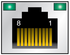
The NET MGT RJ-45 port, located on the rear panel, provides an optional Ethernet connection to the SP. The NET MGT port is an optional connection to Oracle ILOM on the SP. The SP NET MGT port uses an RJ-45 cable for a 1000BASE-T connection (auto-negotiates to 10 Mb/sec, 100 Mb /sec, and 1 Gb/sec, full-duplex only). If your network does not use a DHCP server, this port will not be available until you configure network settings through the SER MGT port.

|
Gigabit Ethernet Ports
Four RJ-45 Ethernet ports (NET 0, NET 1, NET 2, NET 3) can be accessed from the rear panel. See Rear Panel Components. The Ethernet interfaces operate at 100 Mbps, 1000 Mbps, and 10000 Mbps.

|
VGA Port
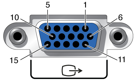
The server has one 15-pin VGA video port on the rear of the server. See Rear Panel Components. Use a DB-15 video cable to connect to a video adapter to achieve the required connection. Maximum supported resolution is 1024 x 768.
Note - The cable length used to connect between the monitor and the VGA port should not be over 6 meters.

|
SAS Ports
The eight SAS connectors are located on the drive backplane inside the server. Four of the connectors also can be used by NVMe drives.

The following table lists the pinouts for the SAS connector.
|