Replace the Midplane Assembly
 | Caution - Hazardous voltage. Possibility of electrical shock if the power cables are connected to the server when accessing the midplane and bus bar assembly. This is a cold-service procedure. Disconnect all power cables before removing the server access panels. |
This procedure requires that the server is removed from the rack. Removing all front-side and back-side components lessens the weight of the server.
Use this procedure to replace a failed bus bar midplane assembly.
Before You Begin
This procedure requires a Phillips screwdriver.
- Prepare the server for cold service. See Prepare the Server for Cold Service.
- At the front of the server, remove all eight fan modules. See Remove a Fan Module.
- Remove both fan frames. See Remove a Fan Frame.
- Remove the CMODs. See Remove a CMOD.
- Remove the four PSUs. See Remove a PSU.
- Remove the FIM. See Remove the FIM.
-
At the rear of the server, remove any cables attached to the rear of the
server.
Before removing cables, label each one, noting its connection point.
- Remove the SMOD. See Remove the SMOD.
-
Remove the DPCCs. See Remove a DPCC.
Before removing the DPCCs, label each one populated with PCIe cards, noting its slot location. For slot designations, see DPCC and PCIe Card Slot Designations.
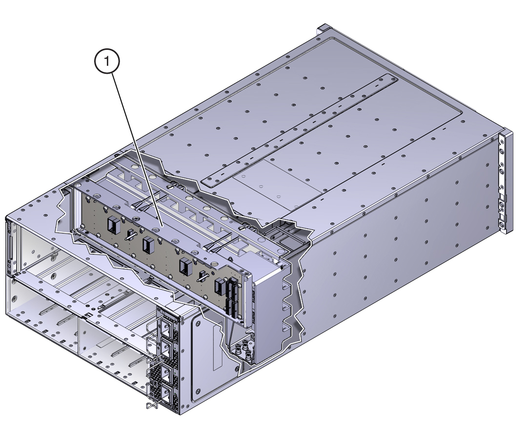
The midplane assembly is located inside the server. In the following illustration, call out 1 shows the location of the midplane assembly.
- Remove the eight screws that secure the server to the rack at the front of the server.
- Use a lift to remove the server from the rack.
-
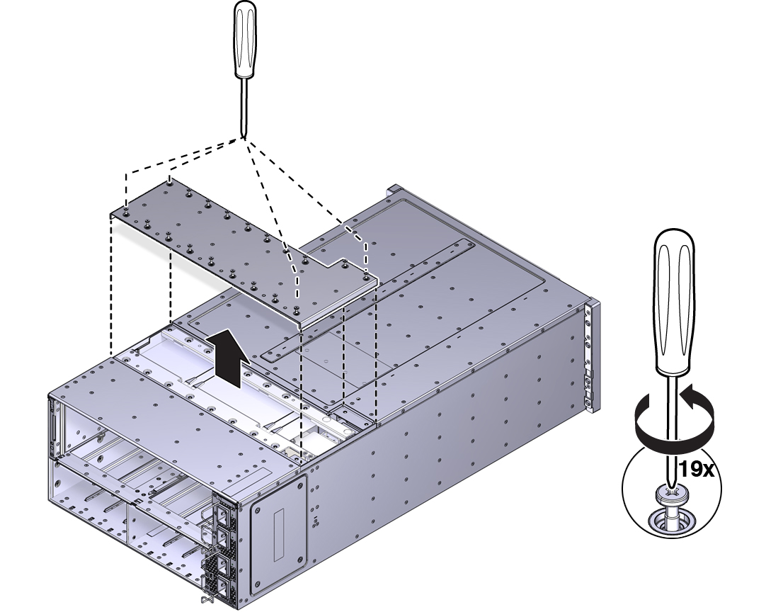
Loosen the 19 captive screws on the top access panel and remove the
panel.
-
Carefully remove and retain the protective black plastic insert that covers
the top of the midplane assembly.
Note the orientation of the insert with respect to the opening. The insert is fitted to the opening using tabs and flaps.
-
Loosen the four captive screws that secure the left side (from the front)
access panel and remove the panel.
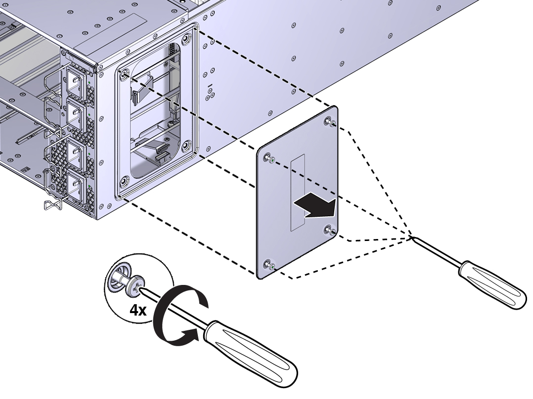
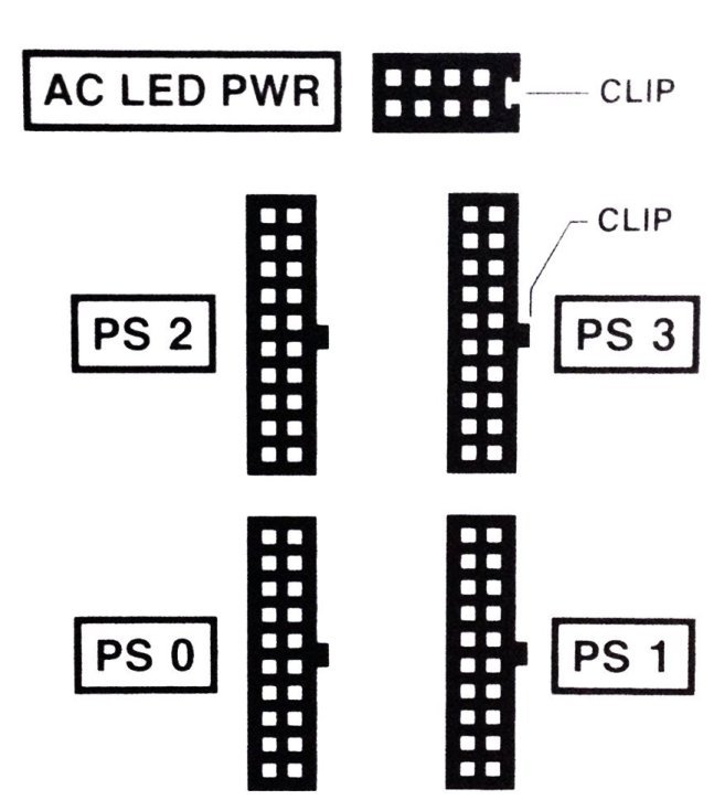
The opening behind the access panel provides access to five cables (four 20-pin PSU cables and one 8-pin cable for the AC power indicator LEDs) that are routed through the server and are connected to the back side of the midplane assembly. To remove the midplane assembly, disconnect these connectors. As an aid, a label on the side of the chassis shows the arrangement and labeling of the five connectors.
The following illustration shows a portion of the label.
-
Reach into the side access opening and disconnect the five connectors from the
back of the midplane assembly.
Tip - To see the connectors, direct the light from a flashlight through the small opening in the top access just above the cable connect points.The following illustration shows the location and arrangement of the connectors on the back of the midplane.
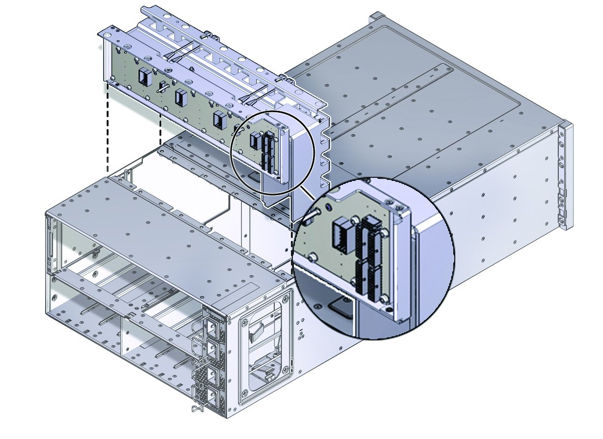
-
Lift the midplane assembly out of the server chassis from the top access
opening.
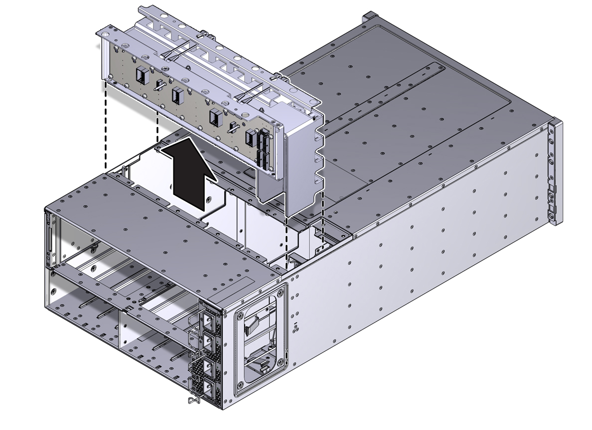
-
Position the cables so the connectors are hanging outside of the server
chassis's side access opening.
The cables inside the chassis should lie flat, so they are not damaged during the installation of the replacement midplane assembly.
- Align and position the replacement midplane assembly in the opening in the top of the server.
-
Carefully lower the midplane assembly into the server until the top of the
assembly is flush with the top of the server.
Take care not to damage the cables and connectors when lowering the midplane assembly into the server.
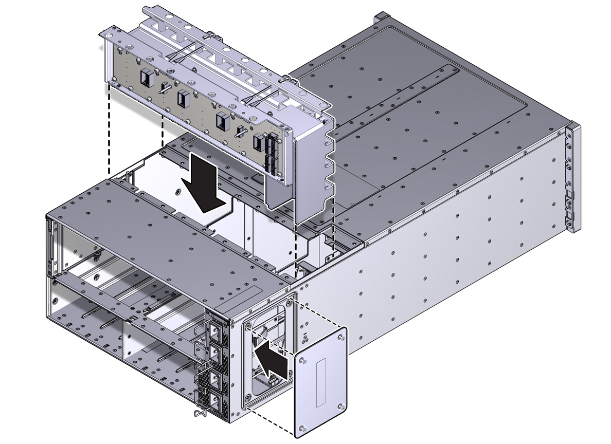
-
Connect the five cables to the connectors on the back of the midplane
assembly.
Ensure that the connectors are positioned correctly, so the key (protrusion) on the side of the connector is aligned with the notch in the connector on the midplane assembly. For best access and visibility, first attach the cable labeled PS 0, then PS 2, followed by PS 1, and finally PS 3. Attach the cable for the AC power indicator board last.

- Position the side access cover at the access opening, ensuring that the four captive screws are aligned with the holes in the side of the chassis.
- To secure the access cover to the chassis, tighten the four captive screws.
-
Install the black plastic insert over the top of the midplane assembly.
Ensure that the orientation of the insert is correct. The insert is fitted to the opening using tabs and flaps.
- Align the top access cover with the opening in the top of the chassis.
-
To secure the cover to the chassis, tighten the 19 captive screws.
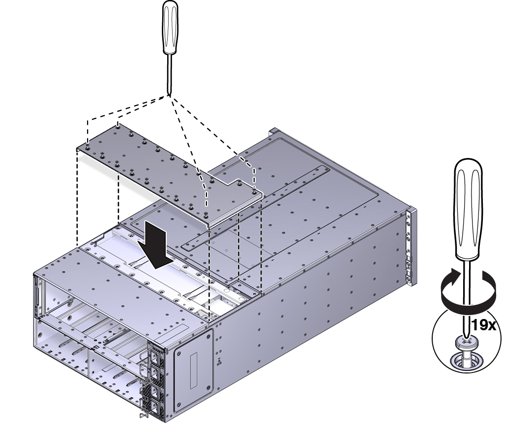
- Install the chassis in the rack.
-
At the front of the server:
-
Install the CMODs. See Install a CMOD.
Your server might have four CMODs, or it might have eight.
- Install both fan frames. See Install a Fan Frame.
- Install all eight fan modules. See Install a Fan Module.
- Install the FIM. See Install the FIM.
- Install the four PSUs. See Install a PSU.
-
Install the CMODs. See Install a CMOD.
-
At the rear of the server:
- Install the SMOD. See Install the SMOD.
-
Install the DPCCs. See Install a DPCC.
For slot designations, see DPCC and PCIe Card Slot Designations.
- Attach cables to their respective connectors and ports at back side of the server.
- Prepare the server for operation. See Returning the Server to Operation.