System Management Subsystem
The system management subsystem includes the buttons, switches, and indicators on the front and back of the server, and the embedded server management software, Oracle System Assistant and Oracle ILOM:
Front Indicator Module (FIM) Panel
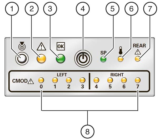
The front indicator module (FIM) panel is located at the top left corner of the server (as viewed from the front of the server). It contains indicators and buttons that allow you to manage the server and determine its status.
The top half of the FIM contains the following row (from left to right) of buttons and indicators:
-
Locator indicator and button
When activated remotely, it helps you find the server in a rack or room of servers. For more information about managing the Locator indicator remotely and locally, see Managing the Locator Indicator.
-
Service Action Required indicator (amber)
When lit, it indicates that a system fault has occurred. Other amber (fault) indicators might also be lit, which can help you isolate the fault to a particular subsystem. For more information about using the Service Action Required and subsystem fault indicators, see Troubleshooting Indicators.
-
Power OK indicator (green)
Along with the SP indicator (below), it provides the status of the system power. For more information about using the Power and SP indicators to determine power state, see Troubleshooting Indicators.
-
Power button
Use it to manage power locally, when at the server. The duration of the button press determines the type of power off (graceful or immediate). For more information about using the Power button, see Powering Off the Server and Power On the Server.
-
Service processor (SP) indicator (green)
Along with the Power OK indicator (above), it provides the status of the system power. For more information about using the Power and SP indicators to determine power state, see Troubleshooting Indicators.
-
Server over-temperature indicator (amber)
When lit, it indicates that a fault has occurred in the cooling subsystem. The system Service Action Required indicator might also be lit. For more information about using the subsystem fault indicators and the system Service Action Required indicator, see Troubleshooting Indicators.
-
Back Service Action Required indicator (amber)
When lit, it indicates that a fault has occurred to one of the components on the server rear (SMOD, DPCC, PCIe card, or HBA). Other indicators (status and fault) might also be lit or in non-normal operating condition state (for example, if the rear SP fault indicator is lit, the system might not be able to boot and the Power OK indicator might not turn on). For more information about using the subsystem fault indicators and the system Service Action Required indicator, see Troubleshooting Indicators.
The bottom half of the FIM contains the CMOD fault indicators, which (from left to right) indicate the status of CMOD 0 - CMOD7. For more information on the CMOD fault indicators, see CMOD Service Action Required Indicators.
The following illustration shows the buttons and indicators on the FIM.
|
CMOD Service Action Required Indicators
The fault indicators for the CMODs are located on the front indicator module (FIM). They are arranged like the CMODs themselves in ascending order from left to right. They light if the corresponding CMOD (0 through 7) is in a fault state.
The following illustration shows the lower section of the FIM and the two groups (left and right) of CMOD Service Action Required indicators.

Power Supply Unit (PSU) Indicators
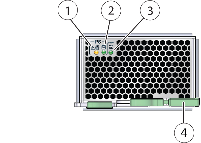
Each power supply unit (PSU) has three indicators arranged in a single row and from left to right as follows:
-
An amber Service Action Required indicator
This indicator lights steady on when the power supply is in a fault state.
-
A green OK indicator
This indicator lights steady on when the PSU is powered on and in a normal functioning state (in this state, the AC indicator is also lit).
-
An AC input indicator
This indicator lights steady on when the PSU is connected to a properly rated AC power source.
The following illustration shows the front of the PSU and the location of the three indicators on the indicator panel (it also shows the location of the release lever).
|
Fan Module (FM) Indicators
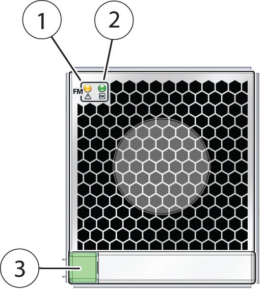
Each fan module (FM) has two indicators arranged in a single row and from left to right as follows:
-
An amber Service Action Required indicator
This indicator lights steady on when the FM is in a fault state.
-
A green OK indicator
This indicator lights steady on when the FM is powered on and in a normal functioning state.
The following illustration shows the front of the FM and the location of the two indicators on the indicator panel (it also shows the location of the release button).
|
Storage Drive Unit Indicators
Storage drives are installed in carriers. Each storage drive carrier has three indicators arranged in a single stacked row and from bottom to top as follows:
-
A green OK/Status indicator
This indicator lights when the storage drive is in a normal functioning state. The light may blink to show activity.
-
An amber Service Action Required indicator
This indicator lights steady on when the FM is in a fault state.
-
A blue Ready to Remove indicator
This indicator is used to show when the storage drive is ready to be removed from the server. Preparing to remove a storage drive is initiated from the server OS.
Note - The storage drive indicators might blink at various rates depending on the activity. For more information on blink rates, see Indicator Blink Rates.
The following illustration shows the front of the storage drive carrier and the storage drive indicators.

|
Back Indicator Panel
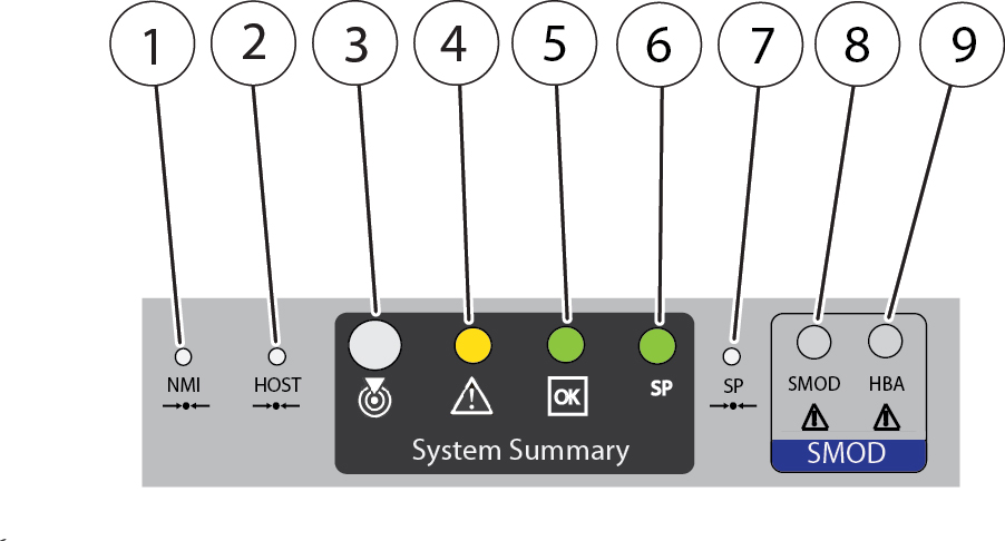
The server has an indicator panel that allows you to manage the server and ascertain its state while servicing it from its back side. The panel is located on the SMOD and includes some indicators and buttons not found on the front indicator module (FIM), including reset switches and indicators for components inside the SMOD. Of the nine switches, indicators, and buttons, four provide a summary of the state of the system, three are switches, and two are for components inside the SMOD.
The following illustration shows the arrangement of the indicators, buttons, and switches on the back indicator panel.
|
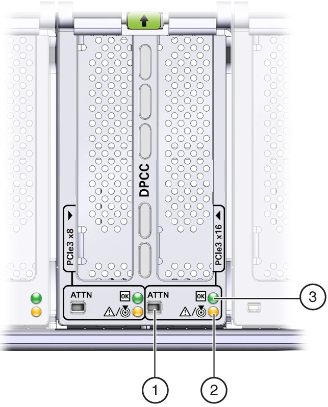
Dual PCIe Card Carrier (DPCC) Indicators
Each DPCC has two indicator panels, one for each PCIe slot inside the server. Each panels contains a green OK indicator, an amber Service Action Required indicator, and a recessed pinhole switch.
|
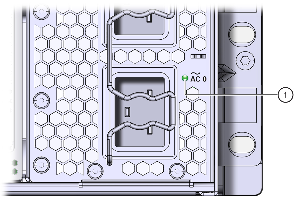
AC Power Inlet Indicators
Each power inlet on the AC power block at the back of the server has an indicator panel. The panel has a single green OK indicator that turns on steady only when the power at the connector is sufficient for the power supply unit. In the following illustration, call out 1 shows the OK indicator for inlet AC 0.
Switches and Buttons
When you are at the server, the following switches and buttons are accessible:
-
Front panel Power button
Allows you to control server power while local to (at) the server. For power off information, see Powering Off the Server. For power on information, see Power On the Server.
-
Two Locator indicator buttons (one on the front of the server and one on the back)
The buttons allow you to manage the Locator indicator locally. To deactivate (or activate) the Locator indicator, press and release the button (see Managing the Locator Indicator).
-
Service processor (SP) pinhole reset switch on the back of the server
The SP reset switch allows you to manually reset the SP. Use the reset button if the SP becomes unresponsive, requires a reset, or fails to boot into standby power mode (activating the button requires the use of a stylus).
For switch location information, see Back Indicator Panel.
-
Host pinhole reset switch on the back of the server
The Host Reset switch allows you to perform a graceful shutdown of the server (activating the button requires the use of a stylus).
For switch location information, see Back Indicator Panel.
-
NMI pinhole switch on the back of the server
The NMI switch is used by Service personnel only. Do not press.
For switch location information, see Back Indicator Panel.
-
CMOD Fault Remind button
Each CMOD has a motherboard-mounted Fault Remind button. The button is part of the CMOD Fault Remind circuit. The circuit is charged and allows you to identify a failed DIMM or CPU after the CMOD has been removed for the server.
For button location information, see CMOD Layout.
-
Sixteen (16) recessed ATTN (attention) buttons (two on each DPCC)
The buttons are used to initiate DPCC removal and install. Before removing a DPCC, use a stylus to press both ATTN buttons. After installing a DPCC that contains a PCIe card, press the button again.
For button location information, see Front Indicator Module (FIM) Panel and Back Indicator Panel.
Service Processor (SP) Oracle ILOM
The server System Module (SMOD) contains a Pilot 3 service processor (SP) that runs Oracle ILOM. Oracle ILOM allows you to manage and monitor the server locally or remotely in full power or standby power modes. Local and remote interface and control connections to the SP are on the back of the server and include a RJ45 GigabitEthernet port (remote access) and an RJ45 serial connector and DB15 VGA connector (local access). For information about Oracle ILOM, including initial release version and update information, see the Sun Server X4-8 Product Notes.
Oracle System Assistant
Your server might also come equipped with Oracle System Assistant. Oracle System Assistant is a server provisioning and update tool that assists in initial server set up and OS installation and allows you to easily manage server updates. As an option, Oracle System Assistant is delivered on a USB storage drive that is factory-installed in the internal USB slot, P0. The drive is configured at the factory with a server-specific version of Oracle System Assistant. You can start Oracle System Assistant from the server boot screen or from Oracle ILOM.
With Oracle System Assistant, you can:
-
Get a single server-specific bundle of the latest available BIOS, Oracle ILOM, and hardware firmware and the latest tools and OS drivers from the Oracle support site.
-
Update OS drivers and component firmware and configure RAID.
-
Install supported operating systems with the latest drivers and supported tools.
-
Configure a subset of Oracle ILOM settings.
-
Save and restore customized BIOS settings or revert the BIOS to the factory defaults.
-
Access embedded product documentation.
-
Display system overview and detailed hardware inventory information.
For more information, refer to the Oracle x86 Administration Guide for X4 Series Servers at: https://www.oracle.com/goto/x86admindiag/docs