Go to main content

Sun Server X4-8 Service Manual

Exit Print View

Updated: March 2018


BIOS Setup Utility Screens

The initial navigation of the BIOS Setup utility is through the tabs, which each open one of the top level screens. The following table lists and describes the tabs and the corresponding screens.

Menu
Description
Main
General system and product information, including date and time, security, hardware configuration and CPU, and DIMM information.
Advanced
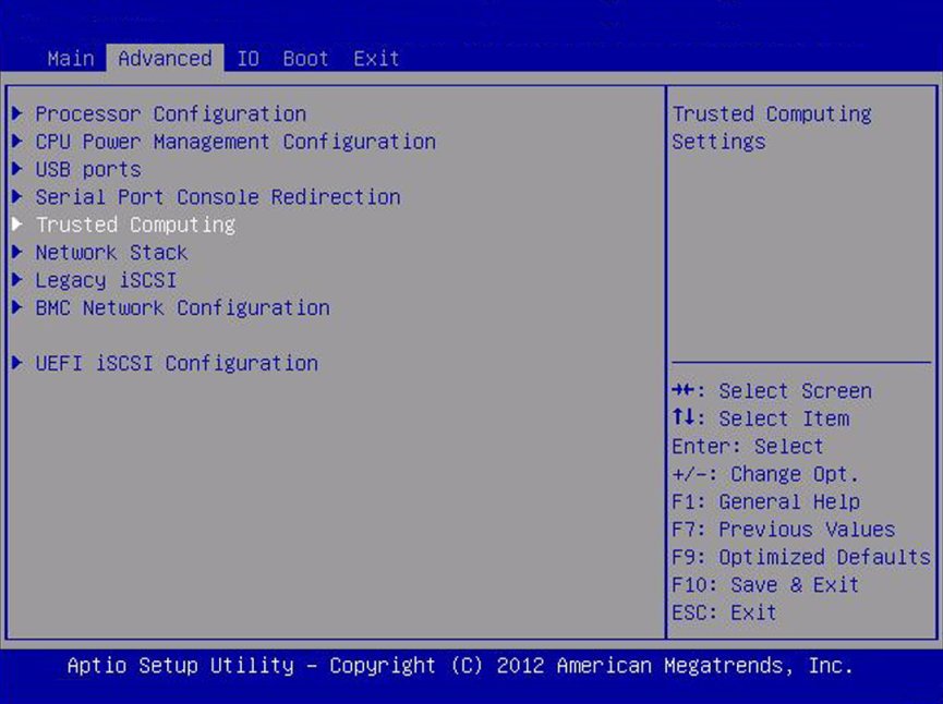
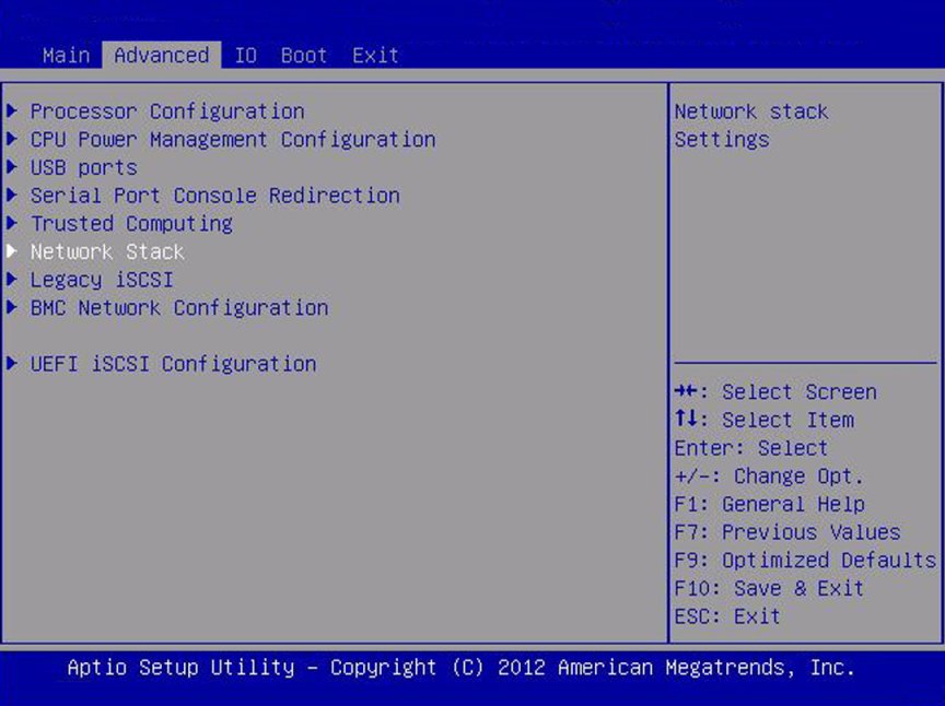
Configuration information for processors, CPU power management, USB ports, serial ports, trusted computing, network stack, legacy iSCSI, BMC network configuration, and UEFI iSCSI configuration.
IO
Configuration interface for plug-and-play (PnP) devices, virtualization, internal devices,and add-in cards.
Boot
Configuration interface for boot settings, including boot mode (Legacy or UEFI), Oracle System Assistant Configuration, and boot option priority.
Exit
Saves or discards changes.

This section contains screen captures of BIOS Setup utility screens. To access the BIOS Setup utility, see Access the BIOS Setup Utility.

The following sections describe each of the top-level BIOS screens. Each section includes a picture of the screen and a table describing the selectable items on the screen.

Other items on the screen either provide additional information, or open another screen.

Main Screen (Legacy)

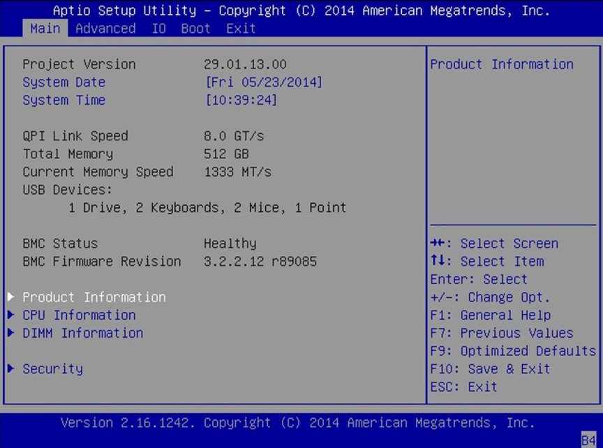
The following table describes the selections on the BIOS Main screen.

image:A screen capture showing the BIOS Utility Main screen.
Main Setup Options
Options
Description
Project Version (R/O)
BIOS version. This string is a unique identifier used to reference a specific BIOS release. Format is XXYYZZPP, which indicates:
XX - Unique project/platform code.
YY - BIOS major release.
ZZ - BIOS minor release. PP - Build number.
Example: 18.01.04.01 System Date
System Date
Current date. You can change the date setting. Example: [Thu 03/05/2013]
System Time
Current time. You can change the time setting. Example: [13:38:27]
QPI Link Speed (R/O)
SLOW,
6.4 GT/s
7.2 GT/s
8.0 GT/s
Intel Quick Path Interconnect (QPI) operational speed.
Total Memory (R/O)
Memory in gigabytes. Example: 64 GB (DDR3)
Current Memory Speed (R/O)
Memory speed. Example: 1333 MHz
USB Devices (R/O)
Detected USB devices. Example: 1 drive, 2 keyboards, 2 Mice, 1 point
BMC Status (R/O)
Normally "Healthy"
BMC Firmware Revision (R/O)
The service processor firmware version. Example: 3.3.2.0 r85361
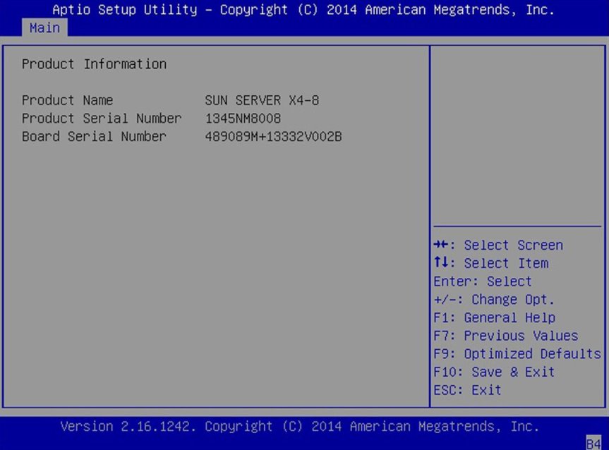
Product Information (R/O)
Product information.
Product Name
Product name. Example: Sun Server X4-8
Product Serial Number
Product serial number. Example: a12345b12345
Board Serial Number
Board serial number. Example: 489089M+11280W0041
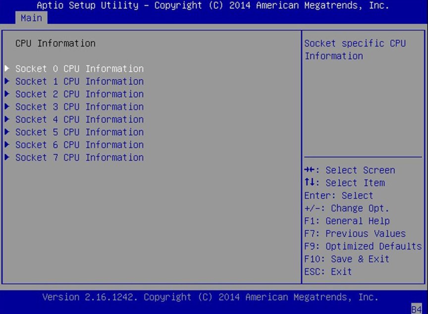
CPU Information (R/O)
Attributes of a single processor (CPU) are defined. A separate information structure is provided for each processor supported in the system. Most of the values are dependent on the processor.
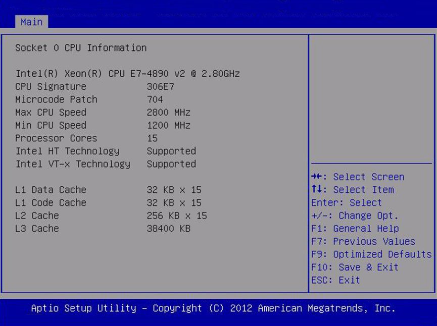
Socket 0 CPU Information
If CPU socket 0 is populated, the following options are listed. Otherwise, displays "Not Present."
Intel CPU @ 2.80 GHz
Processor ID brand.
CPU Signature
Processor (CPU) information. Example: 306E7
Microcode Patch
Software update (microcode patch) information. Example: 704
Max CPU Speed
Maximum non-turbo speed of the processor. Example: 2800 MHz
Min CPU Speed
Minimum speed of the processor.
Processor Cores
Number of available processor cores. Example: 15
Intel HT Technology
Indicates whether Intel Hyper Threading is supported.
Intel VT-x Technology
Indicates whether Intel Virtualization Technology is supported.
L1 Data Cache
Example: 32 KB x 15
L1 Code Cache
Example: 32 KB x 15
L2 Cache
Example: 256 KB x 15
L3 Cache
Example: 38400 KB
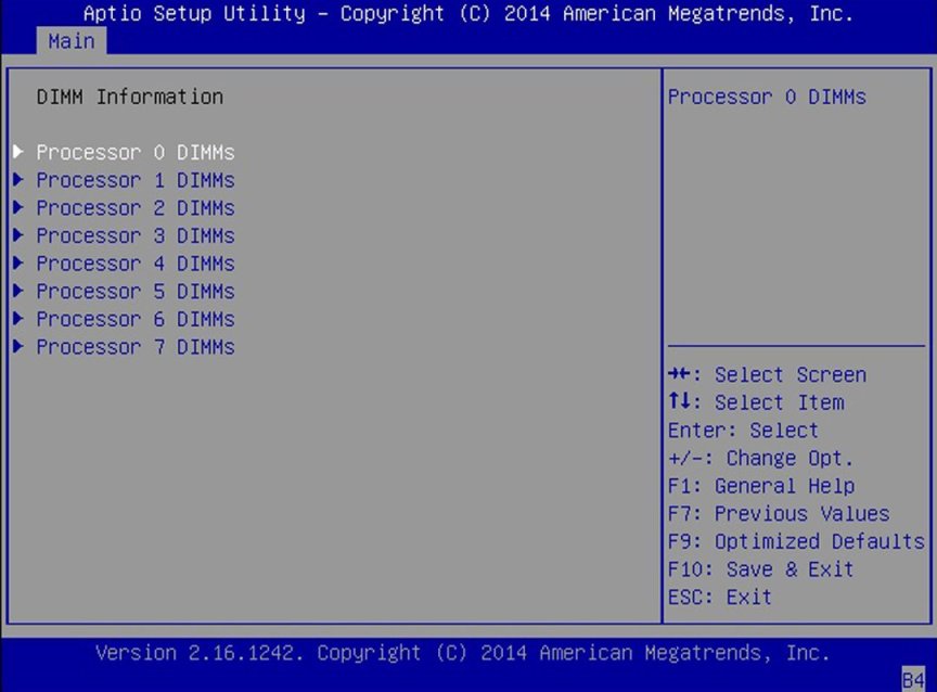
DIMM Information (R/O)
Memory module (DIMM) presence and size information are displayed.
Processor X DIMMs
If DIMM is present, memory size in gigabytes. Otherwise, displays "Not Present."
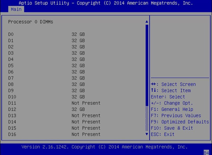
D0...D23
Shows where DIMM is installed and memory size in gigabytes. Example:
Processor 0 DIMMs
D0 – 32 GB
D1 – 32 GB
D2 – 32 GB
D3 – 32 GB
D4 – 32 GB
D5 – 32 GB
D6 – 32 GB
D7 – 32 GB
D8 – 32 GB
D9 – 32 GB
D10 – 32 GB
D11 – Not present
D12 – 32 GB
D13 – Not present
D14 – Not present
D15 – Not present
D16 – Not present
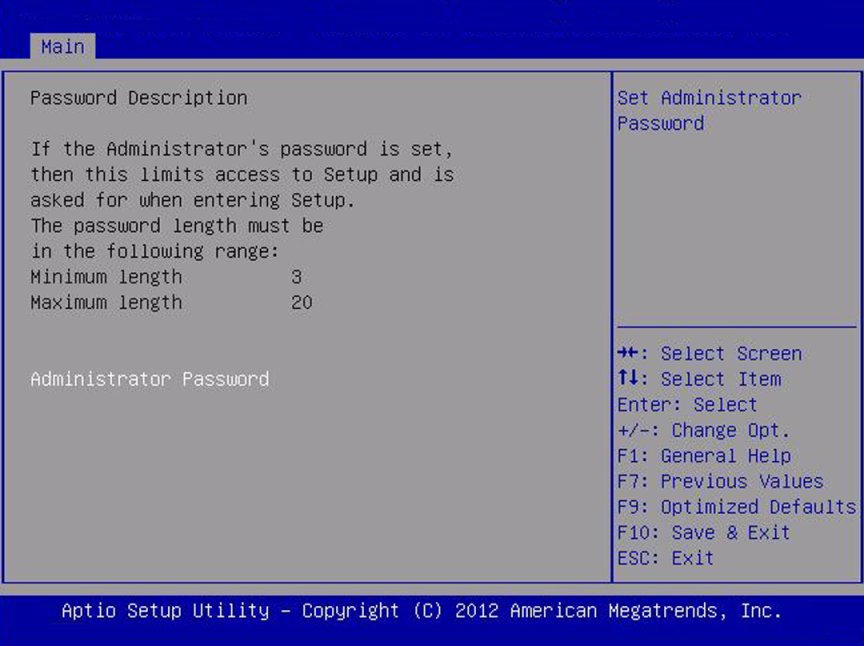
Security Setting
Configure the security setting.
Administrator Password
Set the Administrator password.
image:A screen capture showing the Product Information screen. image:A screen capture showing the CPU Information screen. image:Screen capture showing Socket 0 CPU information image:A screen capture showing DIMM information. image:A screen capture showing Processor 0 DIMM information. image:A screen capture showing the Security screen.

Advanced Screen (Legacy)

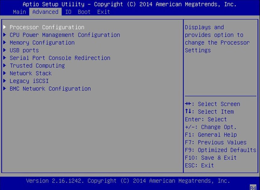
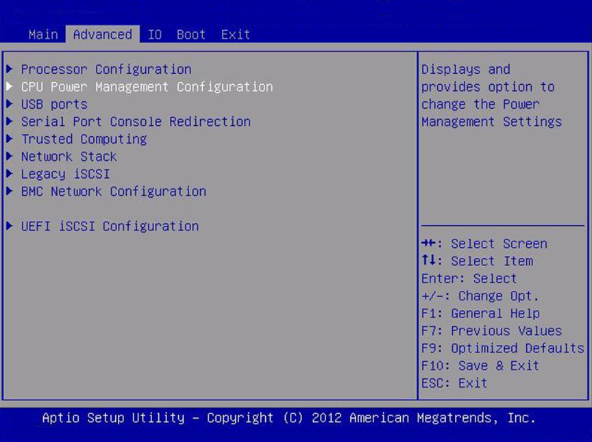
The following sections show the sub-selections on the Advanced screen.

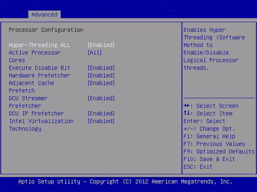
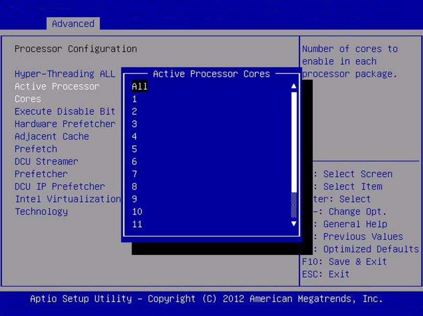
Advanced - Processor Configuration

image:Screen capture showing the legacy mode Advanced screen.
Advanced Setup Options
Options
Defaults
Description
Processors
Enable or disable processor (CPU) features.
Hyper-threading
Disabled/Enabled
Enabled
When enabled, two threads are available per enabled core. When disabled, only one thread per enabled core is available.
Execute Disable Bit
Disabled/ Enabled
Enabled
When enabled, execute disable bit can prevent certain classes of malicious buffer overflow attacks when combined with a supporting OS (Oracle Solaris, Oracle VM, Windows Server, Red Hat Enterprise Linux, SUSE Linux Enterprise Server, and VMware ESXi).
Hardware Prefetcher
Disabled/ Enabled
Enabled
Enable the mid-level cache (L2) streamer prefetcher.
Adjacent Cache Line Prefetch
Disabled/ Enabled
Enabled
Enable the mid-level cache (L2) prefetching of adjacent cache lines.
DCU Streamer Prefetcher
Disabled/ Enabled
Enabled
Enable prefetching of next L1 data line based on multiple loads in same cache line.
DCP IP Prefetcher
Disabled/ Enabled
Enabled
Enable prefetching of next L1 line based on sequential load history.
Intel Virtualization Technology
Disabled/ Enabled
Enabled
When enabled, a Virtual Machine Manager (VMM) can utilize the additional hardware capabilities provided by Intel Virtualization Technology.
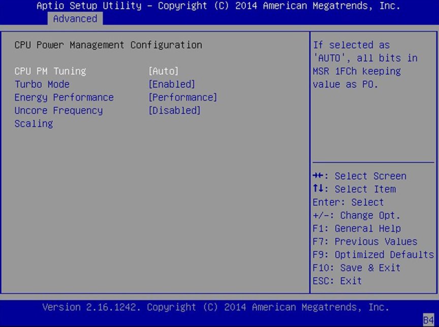
CPU Power Management Configuration
Displays processor (CPU) information. BIOS provides C-states, P-states, and T-states support in order for the OS to manage the power utilization of the system. Power management is also controlled by the service processor based on system policies.
Power Technology
Disabled/ Enabled/
Efficient/ Custom
Efficient
Enable the power management features. The following options are not displayed if Power Technology is set to Disabled.
Intel SpeedStep
Disabled/ Enabled
Enabled
Displays only if Power Technology is set to Custom. Enable or disable Intel SpeedStep. The Intel technology used to support P-state transitions is referred to as Intel SpeedStep.
CPU C3 Report
Disabled/ Enabled
Enabled
Displays only if Power Technology is set to Custom and power state (C3) is supported by the CPU. Enable or disable CPU C3 (ACPI C2) report to the operating system.
Turbo Mode
Disabled/ Enabled
Displays only if Power Technology is set to Custom, Intel SpeedStep is set to enabled, and TurboMode is supported in the CPU.
Energy Performance
Performance/ Balanced Performance
Balanced Performance
Optimize between performance and power savings. Windows 2008 and later operating systems override this value according to its power plan.
Uncore Frequency Scaling
Disabled/ Enabled
Disabled
Frequency scaling for the uncore portion of the CPU.
When Enabled allows uncore portions (I/O) of the CPU to change frequencies along with CPU cores when P-States are changed. If Disabled, uncore portions are not affected by P-State changes.
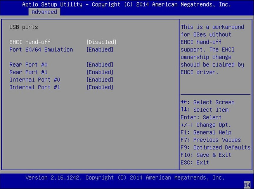
USB Ports
Set USB port configuration parameters.
EHCI Hand-off
Disabled/ Enabled
Disabled
Enable or disable Enhanced Host Controller Interface (EHCI) hand-off support.
Port 60/64 Emulation
Disabled/ Enabled
Enabled
Enable I/O port 60h/64h emulation support. Enable this setting for the complete USB keyboard legacy support for non-USB aware operating systems.
Rear Port 0
Disabled/ Enabled
Enabled
Enable or disable rear USB Port 0.
Rear Port 1
Disabled/ Enabled
Enabled
Enable or disable rear USB Port 1.
Internal Port 0
Disabled/ Enabled
Enabled
Enable or disable internal USB Port 0. By default, internal port 0 is reserved for Oracle System Assistant.
Internal Port 1
Disabled/ Enabled
Enabled
Enable or disable internal USB Port 1.
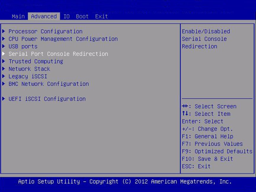
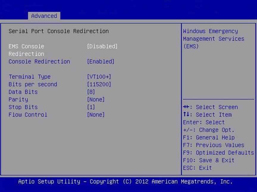
Serial Port Console Redirection
Provides the capability to redirect console output/input to the serial port. Graphic output is not redirected. BIOS serial console redirection lets you monitor BIOS POST messages and navigate the BIOS Setup utility menus and Option ROMs from a terminal connected to the server using a serial connection.
EMS Console Redirection
Disabled/ Enabled
Disabled
Enable or disable console redirection for Windows Emergency Management Service (EMS) administration.
Console Redirection
Disabled/ Enabled
Enabled
Enable or disable console redirection.
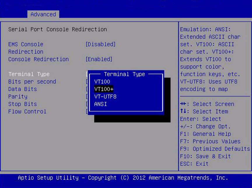
Terminal Type
VT100/
VT100+/
VT-UTF8/
ANSI
VT100+
Select the emulation for the terminal: VT100: ASCII character set. VT100+: Extends VT100 to support color, function keys, etc. VT-UTF8: Uses UTF8 encoding to map Unicode characters onto one or more bytes. ANSI: Extended ASCII character set.
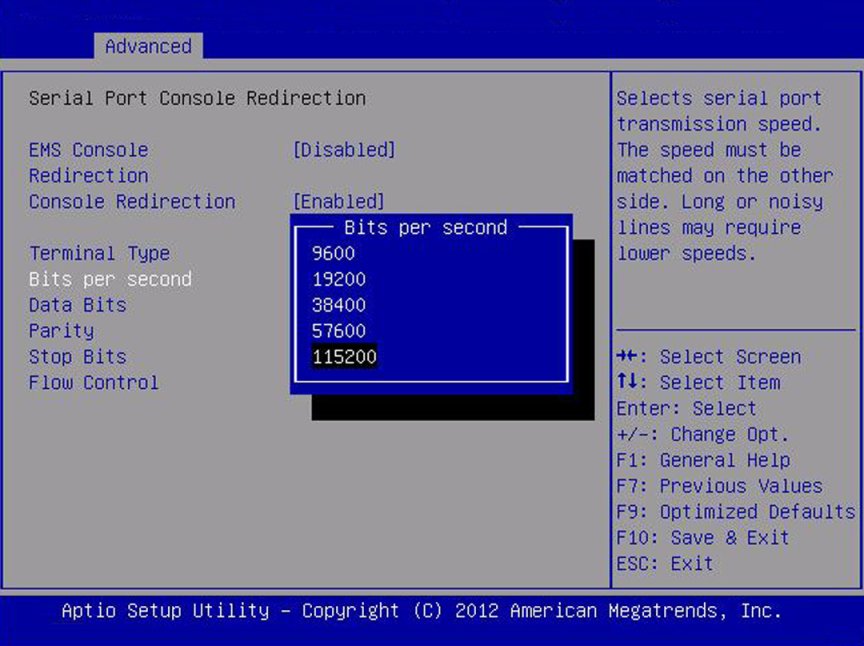
Bits per Second
9600/ 10200
/ 57600/ 115200
9600
Select the serial port transmission speed. The speed must be matched on the connecting serial device. Long or noisy lines require lower speeds.
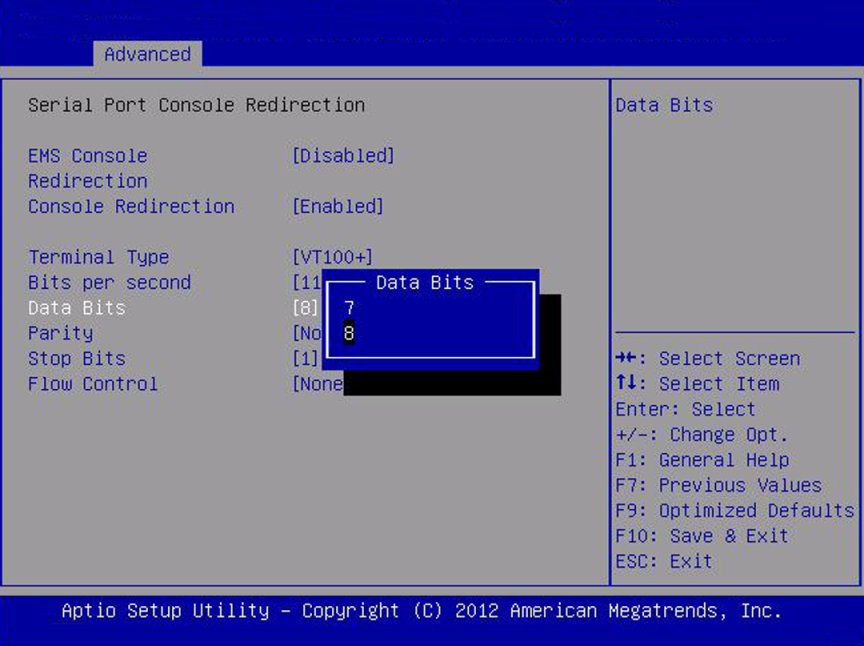
Data Bits
07/08/11
8
Select the data bits.
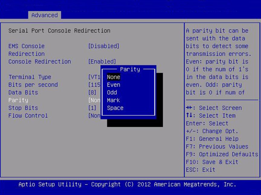
Parity
None/
Even/
Odd/
Mark/
Space
None
A parity bit can be sent with the data bits to detect some transmission errors.
None: No parity bits are sent.
Even: Parity bit is 0 if the number of 1s in the data bits is even.
Odd: Parity bit is 0 if the number of 1s in the data bits is odd.
Mark: Parity bit is always 1.
Space: Parity bit is always 0.
Mark and Space parity do not allow for error detection. They can be used as an additional data bit.
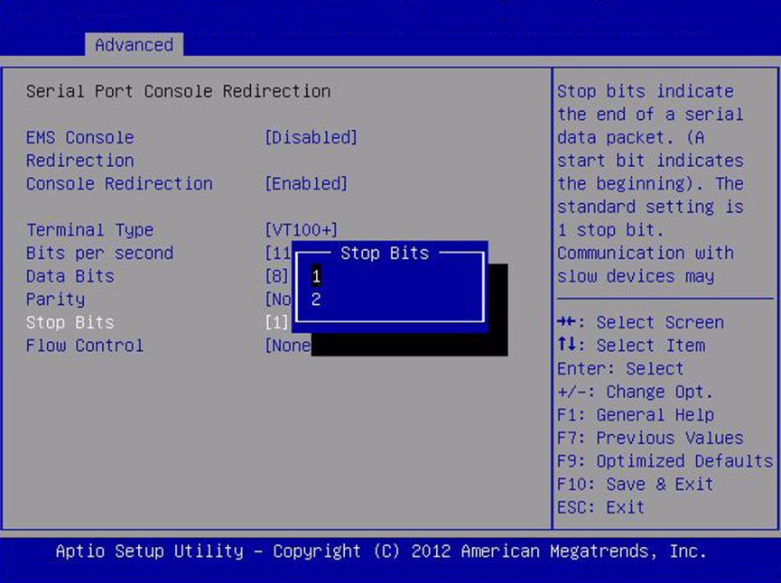
Stop Bits
01/02/11
1
Stop bits indicate the end of a serial data packet. (A start bit indicates the beginning of a serial data packet.) The standard setting is 1 stop bit. Communication with slow devices may require more than 1 stop bit.
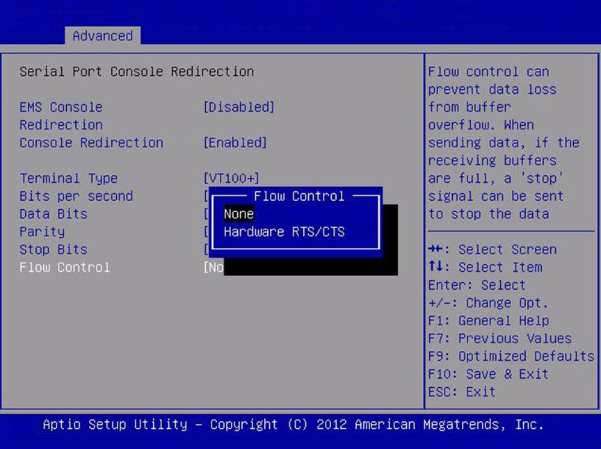
Flow Control
None/
Hardware/
RTS/
CTS
None
Flow control can prevent data loss from buffer overflow. When sending data, if the receiving buffers are full, a "stop" signal can be sent to stop the data flow. Once the buffers are empty, a "start" signal can be sent to restart the flow. Hardware flow control uses two wires to send start and stop RTS (request to send) and CTS (clear to send) signals.
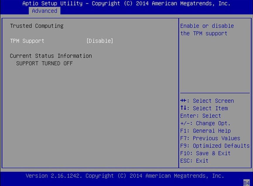
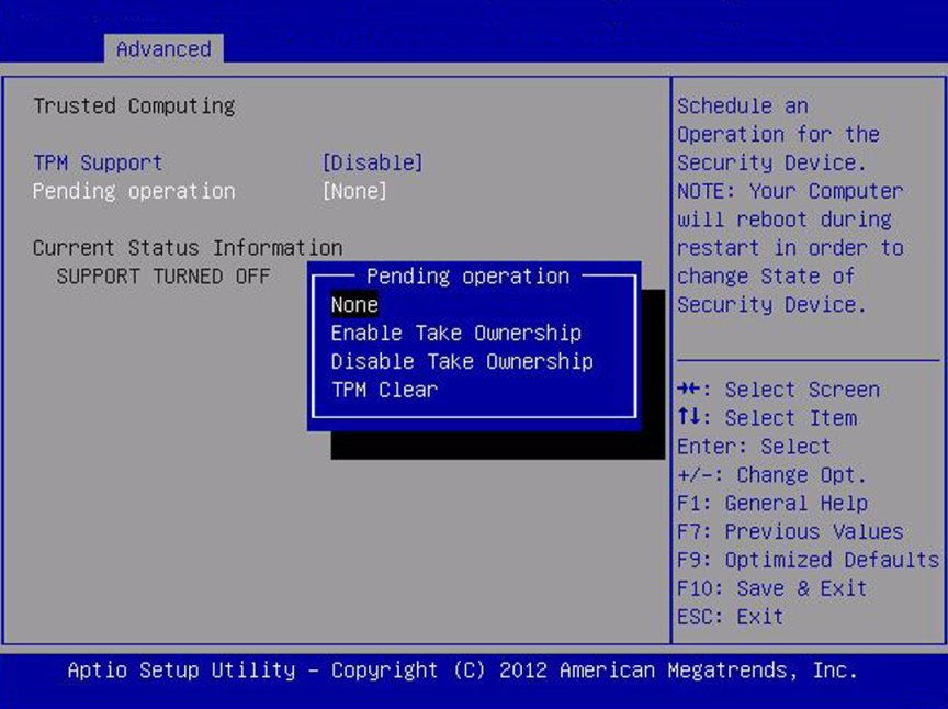
Trusted Computing
If you intend to use the Trusted Platform Module (TPM) feature set, you must configure the server to support TPM. The TPM feature is used by the OS for proof that BIOS code has not been tampered with.
For details on modifying TPM, refer to Oracle x86 Administration Guide for X4 Series Servers at: https://www.oracle.com/goto/x86admindiag/docs
TPM Support
Disabled/ Enabled
Enabled
Enable or disable TPM support. Only UEFI BIOS implements this setup option. If disabled, the OS does not show TPM.
TPM State
Disabled/ Enabled
Disabled
Displays whether TPM Support is enabled.
Current TPM Status Information (R/O)
If TPM Support is disabled, Current TPM Status displays "TPM SUPPORT OFF." If TPM Support is enabled, Current TPM Status displays: TPM Enabled
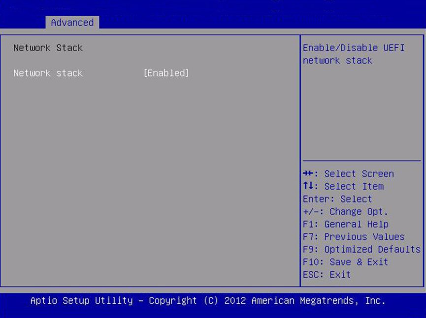
Network Stack
Configure network stack settings.
Network Stack
Disabled/ Enabled
Enabled
Enable or disable the UEFI network stack.
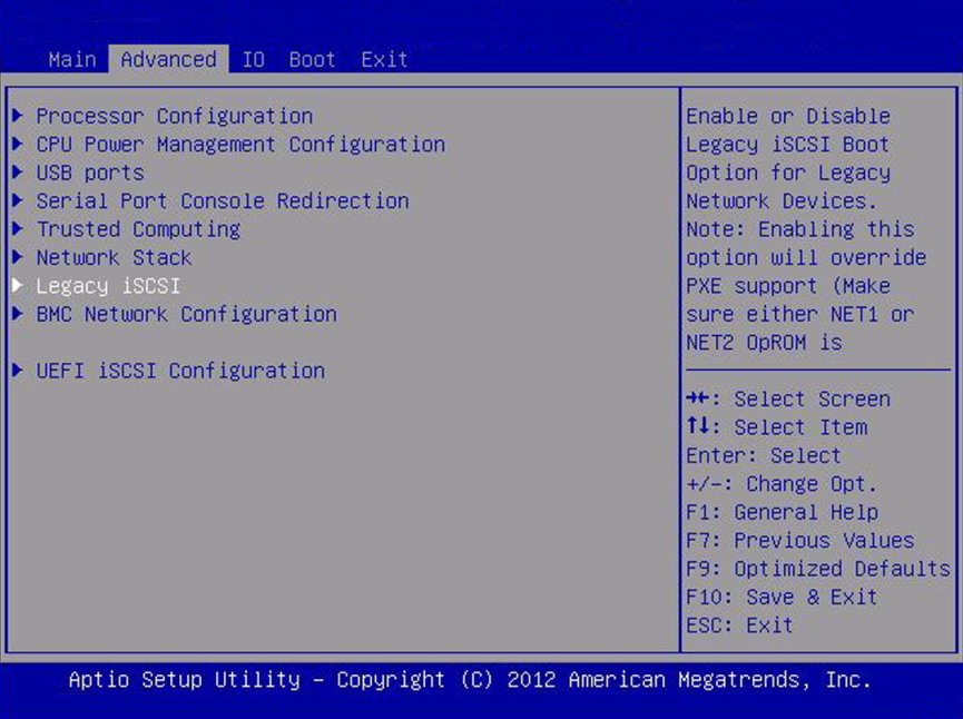
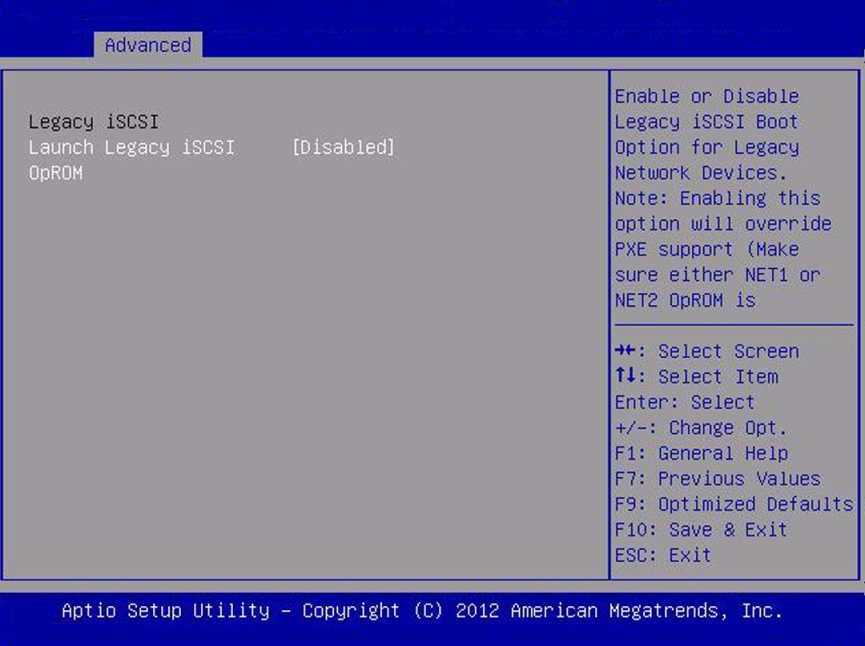
Legacy iSCSI
Enabled allows booting to iSCSI in Legacy Boot Mode.
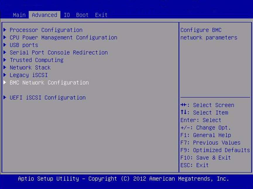
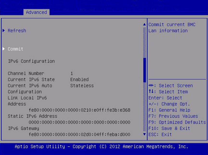
BMC Network
Configure Baseboard Management Controller (BMC) network parameters.
BMC Network: Current Active Management Port (R/O)
Disabled/ Enabled
Enabled
Active management port settings are displayed.
Refresh
Refresh current BMC network information with the latest information from the service processor.
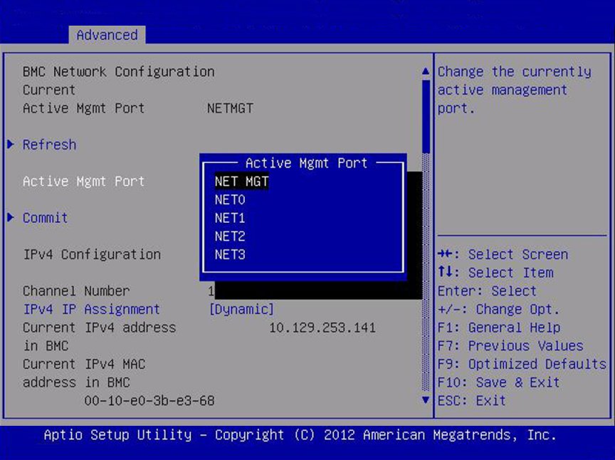
Active Management Port
NETMGT/
NET0/
NET1/
NET2/
NET3
Change the management port that is currently active.
Commit
Commit the current BMC network information.
IPv4 Configuration (R/O)
Current configuration of the IPv4 settings.
Channel Number (R/O)
Current channel number.
IPv4 Assignment (R/O)
Static/Dynamic
Static
View whether the service processor is assigned a static IPv4 address or assigned a dynamic IPv4 address using Dynamic Host Control Protocol (DHCP).
Current IPv4 Address in BMC (R/O)
Current IPv4 address of the service processor. Example: 172.31.255.255
Current IPv4 MAC Address in BMC (R/O)
Current IPv4 MAC address for the service processor. Example: 00:12:46:BE:0A:02
Current IPv4 Subnet Mask in BMC (R/O)
Current IPv4 subnet mask address for the service processor. Example: 255.255.255.0
Refresh
Select Refresh to update to the current settings.
IPv4 Address
If IPv4 Assignment is set to Static, set the IPv4 address for the service processor.
IPv4 Subnet Mask
If the IPv4 Assignment is set to Static, set the IPv4 subnet mask. Example: 255.255.255.0
IPv4 Default Gateway
If the IPv4 Assignment is set to Static, set the IPv4 default gateway. Example: 129.144.82.254
Commit
Commit the IPv4 configuration settings.
IPv6 Configuration (R/O)
Static/Dynamic
Dynamic
Current configuration of the IPv6 settings. IPv6 addresses are written with hexadecimal digits and colon separators. For example: 2001:0db0:000:82a1:0000:0000:1234:abcd. IPv6 addresses are composed of two parts: a 64-bit subnet prefix and a 64-bit host interface ID. To shorten the IPv6 address, you can (1) omit all leading zeros, and (2) replace one consecutive group of zeros with a double colon (::). For example: 2001:db0:0:82a1::1234:abcd
Channel Number (R/O)
1
Current channel number.
Current IPv6 State (R/O)
Current IPv6 state.
Current IPv6 Auto Configuration (R/O)
Current IPv6 autoconfiguration parameters are displayed.
Link Local IPv6 Address (R/O)
Current link local IPv6 address. Example: fe80::214:4fff:feca:5f7e/64
Static IPv6 Address (R/O)
Current static IPv6 address. Example: 2001:0db0:000:82a1:0000:0000:1234:abcd
IPv6 Gateway (R/O)
Current IPv6 gateway address. Example: fe80::211:5dff:febe:5000/128
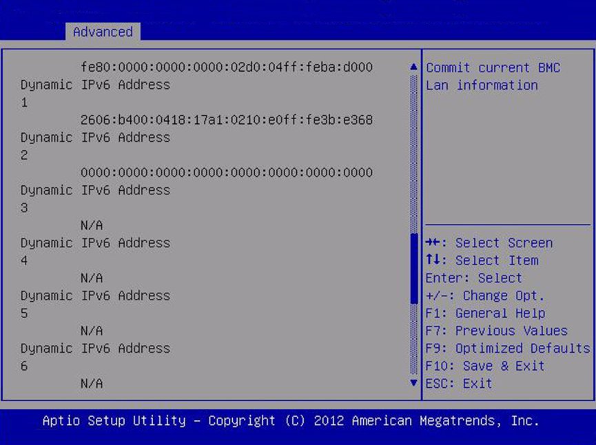
Dynamic IPv6 Address 1 – (R/O)
Current dynamic IPv6 address. Example: fec0:a:8:b7:214:4fff:feca:5f7e/64
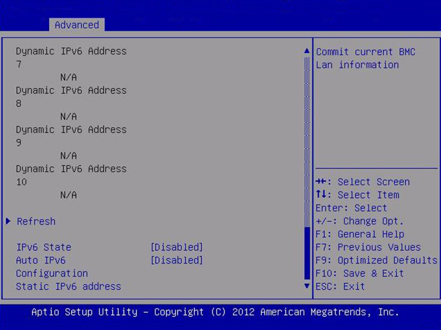
Refresh
Select Refresh to update to the current settings.
IPv6 State (R/O)
Disabled/ Enabled
View whether the IPv6 state is enabled or disabled.
Auto IPv6 Configuration
Disabled/
Stateless/
Dhcpv6_ stateless/
Dhcpv6_ stateful
Disabled
Autoconfiguration options are:
Disabled: When autoconfiguration is disabled, only the Link Local address is set. None of the autoconfiguration options to configure an IPv6 address are run.
Stateless: When enabled, the IPv6 Stateless autoconfiguration is run to learn the IPv6 addresses for the device.
Dhcpv6_stateless: When enabled, the Dhcpv6_stateless autoconfiguration is run to learn the DNS and domain information for the device.
Dhcpv6_stateful: When enabled, the Dhcpv6_stateful autoconfiguration is run to learn the IP addresses and DNS information for the device.
Static IPv6 Address
Set the static IPv6 address. Example: 2001:0db0:000.82a1:0000:0000:1234:abcd
Commit
Commit the IPv6 configuration settings.
image:Screen capture showing the Processor Configuration screen. image:Screen capture showing the Processor Configuration screen.

Advanced - CPU Power Management Configuration

image:Screen capture showing the CPU Power Management Configuration                         screen. image:Screen capture showing the CPU Power Management Configuration                         screen.

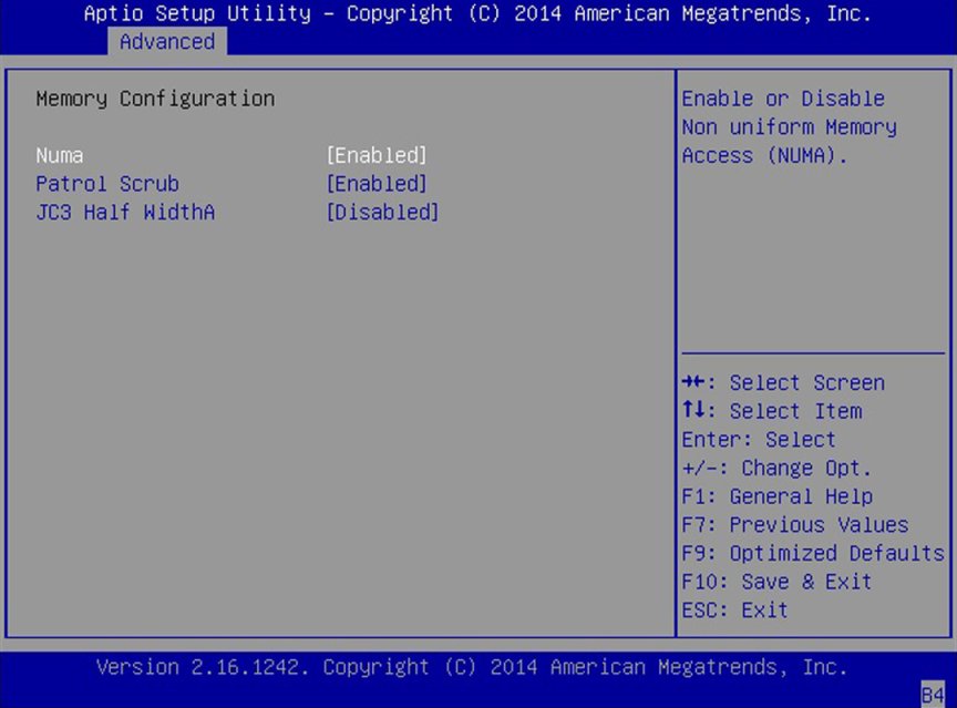
Memory Configuration

image:A screen capture showing the Memory Configuration screen.

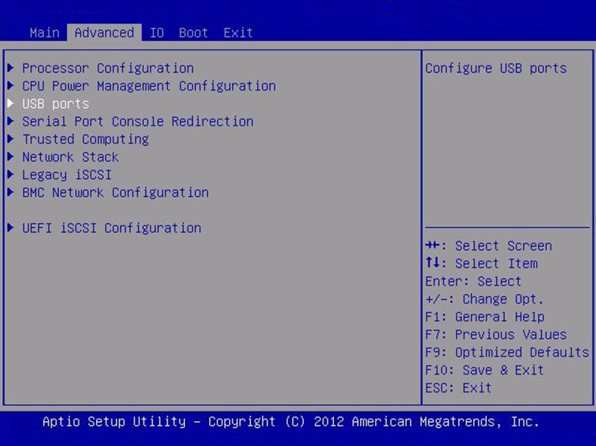
Advanced - USB Ports

image:Screen capture showing the USB ports screen. image:Screen capture showing the USB Ports screen.

Advanced - Serial Port Console Redirection

image:Screen capture showing the Serial Port Console Redirection                         screen. image:Screen capture showing the Serial Port Console Redirection                         screen. image:Screen capture showing the Serial Port Console Redirection                         screen. image:Screen capture showing the Serial Port Console Redirection                         screen. image:Screen capture showing the Serial Port Console Redirection                         screen. image:Screen capture showing the Serial Port Console Redirection                         screen. image:Screen capture showing the Serial Port Console Redirection                         screen. image:Screen capture showing the Serial Port Console Redirection                         screen.

Advanced - Trusted Computing

image:Screen capture showing the Advanced Trusted Computing screen. image:Screen capture showing the Advanced screen. image:Screen capture showing the Advanced Trusted Computing screen.

Advanced - Network Stack

image:Screen capture showing the Network Stack screen. image:Screen capture showing the Network Stack screen.

Advanced - Legacy iSCSI

image:Screen capture showing the Legacy iSCSI screen. image:Screen capture showing the Legacy iSCSI screen.

Advanced - BMC Network Configuration

image:Screen capture showing the BMC Network Configuration screen. image:Screen capture showing the BMC Network Configuration screen. image:Screen capture showing the Commit current BMC LAN information                         screen image:Screen capture showing the commit current BMC Lan information image:Screen capture showing the Commit current BMC Lan information

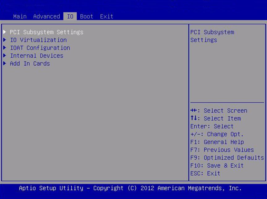
IO Screen

image:A screen capture showing the legacy mode IO BIOS screen.
IO Setup Options
Options
Defaults
Description
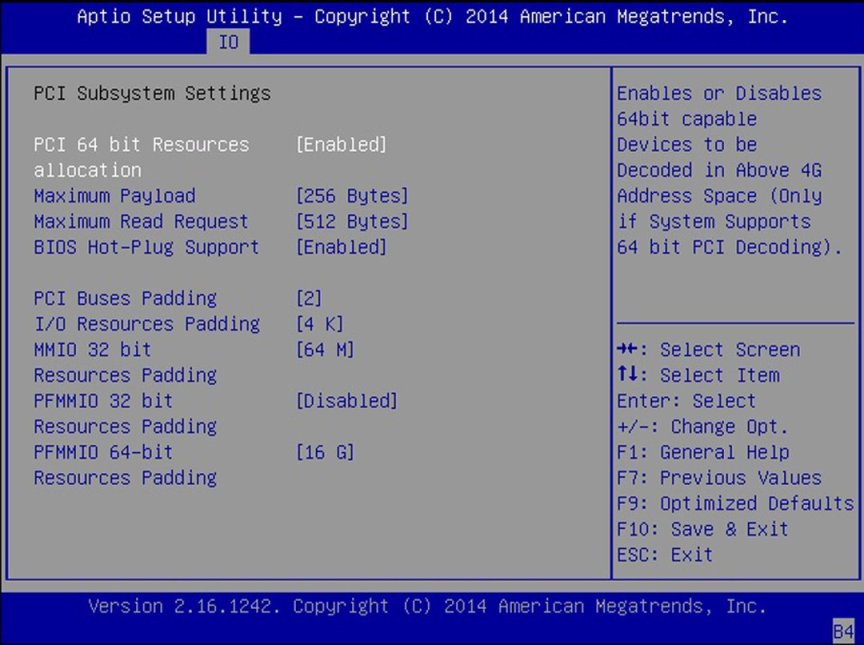
PCI Subsystem Settings
Configure PCI, PCI-X, and PCI Express settings.
PCI 64 Bit Resources Allocation
Disabled/Enabled
Enabled
Enable or disable 64-bit capable devices to be decoded in above 4G address space. This setting is available only if the system supports 64-bit decoding.
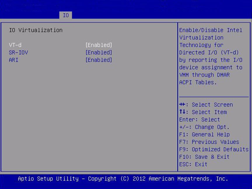
IO Virtualization
Configure single root I/O virtualization settings.
VT-d
Disabled/Enabled
Enabled
Enable or disable Intel Virtualization Technology for directed I/O (VT-d). If enabled, ensures improved isolation of I/O resources for greater reliability, security, and availability.
SR-IOV
Disabled/Enabled
Disabled
Single Root I/O Virtualization (SR-IOV) is used to configure devices into multiple virtual devices that can be used on virtual OS installations. If supported by the hardware and set to enabled, all devices within the system that are SR-IOV capable are configured to support SR-IOV and I/O resources are allocated to the device as normal. If set to disabled, I/O resources are not allocated to the device.
ARI
Disabled/Enabled
Disable
If Alternate Routing ID (ARI) is supported by the hardware and set to enabled, devices are permitted to locate virtual functions (VFs) in function numbers 8 to 255 of the captured bus number, instead of normal function numbers 0 to 7.
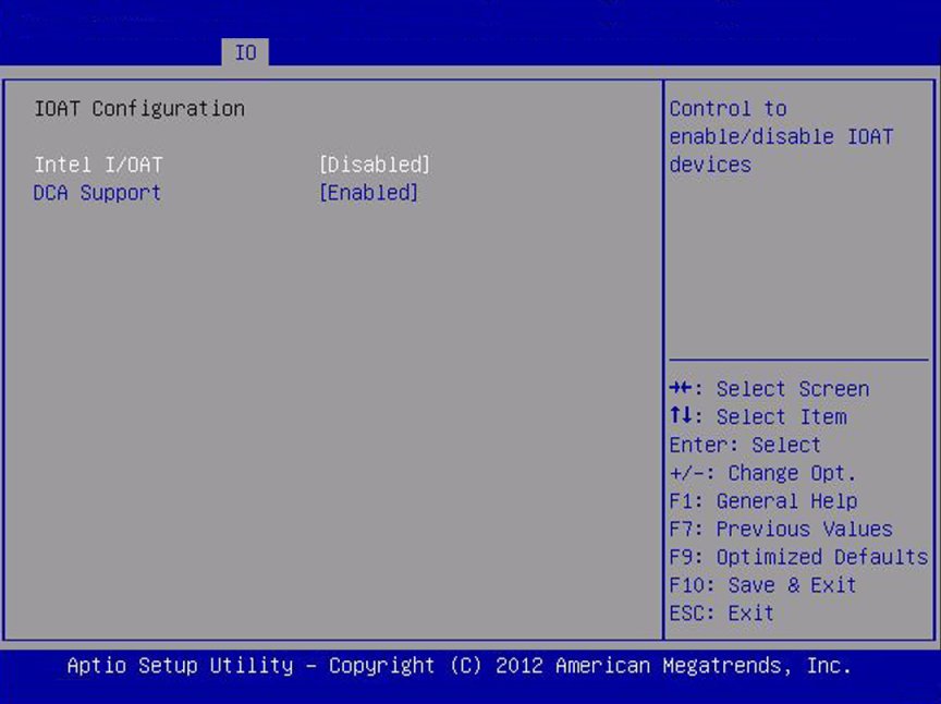
I/OAT
Configure settings for the Intel I/O Acceleration Technology (I/OAT).
Intel I/OAT
Disabled/Enabled
Enabled
Enable or disable Intel I/OAT.
DCA Support
Disabled/Enabled
Enabled
Enable or disable direct cache access (DCA) support.
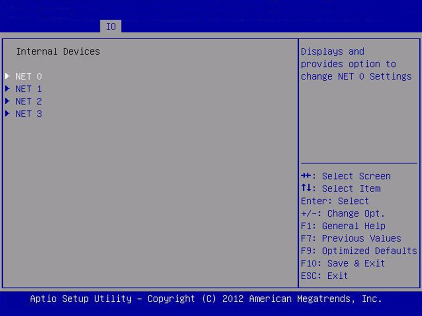
Internal Devices
Configure settings for the embedded network controller.
Net 0/1 OpROM Enable
Disabled/Enabled
Enabled
Enable or disable Option ROM. If set to enabled, Option ROM for the card executes as normal. If set to disabled, Option ROM for the card is not copied into memory and the execution of the Option ROM is inhibited.
Net 2 and Net 3 OpROM Enable
Disabled/Enabled
Enabled
Enable or disable Option ROM. If set to enabled, Option ROM for the card executes as normal. If set to disabled, Option ROM for the card is not copied into memory and the execution of the Option ROM is inhibited.
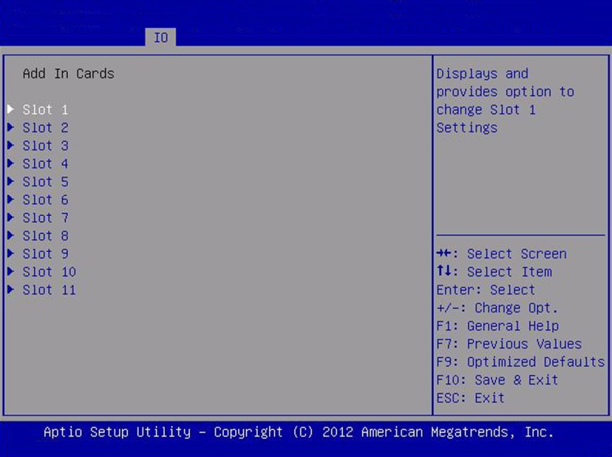
Add-in Cards
Enable or disable the add-in cards.
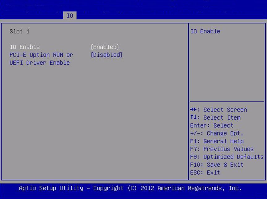
Slot 1
IO Enable
Disabled/Enabled
Enabled
Enable or disable I/O for the add-in card.
OpROM Enable
Disabled/Enabled
Enabled
Enable or disable Option ROM for add-in card.
Slot 2
IO Enable
Disabled/Enabled
Enabled
Enable or disable I/O for the add-in card.
OpROM Enable
Disabled/Enabled
Enabled
Enable or disable Option ROM for add-in card.
Slot 3
IO Enable
Disabled/Enabled
Enabled
Enable or disable I/O for the add-in card.
OpROM Enable
Disabled/Enabled
Enabled
Enable or disable Option ROM for add-in card.
Slot Internal
Disabled/Enabled
Enabled
IO Enable
Disabled/Enabled
Enabled
Enable or disable the I/O for the internal host bus adapter (HBA) card.
OpROM Enable
Disabled/Enabled
Enabled
Enable or disable Option ROM for the internal host bus adapter (HBA) card.
image:Screen capture showing the IO screen PCI Subsystem Settings. image:Screen capture showing IO Virtualization screen image:Screen capture showing IOAT configuration image:Screen capture showing IO internal devices screen image:Screen capture showing PCI-E Option ROM or UEFI Driver Enable                         screen image:Screen capture showing IO Add In cards image:Screen capture showing Slot 1 screen

Boot Screen

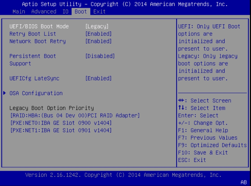
The boot screen differs slightly depending on whether the server is in UEFI boot mode or in legacy boot mode.

image:A screen capture showing the legacy mode Boot BIOS screen.
Option
Default
Description
UEFI/BIOS Boot Mode
Legacy
Select Legacy or UEFI boot mode (UEFI boot mode shown above)
Retry boot list
Enabled
If enabled, BIOS automatically retries to boot from the top of the Boot Options Priority list when all devices have been attempted and failed.
Network Boot Rerty
Enabled
  • If enabled, BIOS automatically retries the PXE list present in the system when all PXE attempts have failed.

  • If disabled, the system halts and displays the error message "Network Boot Failed" when all PXE boots failed.

  • If set to Boot List, fail over to the main Boot Options Priority list.

Persistent Boot Support
Disabled
Allows devices to maintain a position in the boot priority list even after removal so that, if the device is returned, it is not assigned to a lower priority position.
UEFIcfg LateSync
Enabled
Allows synchronization to occur immediately after a BIOS configuration change by automatically rebooting the system.
OSA Configuration > OSA Internal Support
Enabled
Open OSA Configuration screen and toggle OSA Internal Support to enable or disable booting OSA from the internal USB port
Boot Option Priority
Order of discovery by BIOS
Move items up and down the list to change the boot priority order in legacy boot mode.
This list changes when the boot mode changes.