JavaScript is required to for searching.
Skip Navigation Links
Exit Print View
Sun Storage J4500 Array Service Manual
search filter icon
search icon

Document Information

Preface

1.  Introduction to the Sun Storage J4500 Array

1.1 Features

1.2 Exterior Features, Controls, and Indicators

1.2.1 Front Panel

1.2.2 Back Panel

1.2.3 Sun Storage J4500 Array Internal Components

1.3 Accessory Kit

2.  Configuring and Powering On the Sun Storage J4500 Array

2.1 Configuration and Cabling

2.1.1 Terms and Definitions

2.1.2 Configuration Rules

2.1.3 Cabling the SAS Connectors

2.1.4 Example Configurations

2.2 Powering On and Off the Array

To Power On the Array

To Place the Array Into Standby Power Mode

To Power Off the Array

2.2.1 AC Power Failure Auto-Recovery

3.  Maintaining the Sun Storage J4500 Array

3.1 Options and Replaceable Components

3.2 Tools and Supplies Needed

3.3 Powering Off the Array and Removing It From the Rack

To Power Off the Array

To Remove the Array Enclosure From the Rack

3.4 Removing and Replacing the Hard Disk Drive Access Cover

To Remove the Hard Disk Drive Access Cover

To Replace the Hard Disk Drive Access Cover

3.5 Internal Component Locations

3.6 Replacing Components

To Replace a Fan Module

To Replace the Front Indicator Board

To Replace a Hard Disk Drive

To Replace the Power Distribution Board

To Replace a Power Supply

To Replace the System Controller Module

To Replace the Array Chassis

3.7 Upgrading Enclosure Firmware

3.7.1 Ensure Both SAS Fabrics are Upgraded to the Same Firmware Revision Level

4.  Troubleshooting

4.1 External Status LEDs

4.2 Internal Disk Drive and Fan LEDs

4.3 Diagnostic and Management Tools

4.3.1 SunVTS

4.3.2 Common Array Manager (CAM)

4.4 Troubleshooting Problems with the Array

4.4.1 Initial Start-up

4.4.2 Check the Event and Performance Logs

4.4.3 Using the Array Management Software to Monitor Enclosure Health

4.4.4 Array Link Problems

4.4.5 Disk Problems

4.4.6 Array Environment Problems

4.4.7 Power Problems

4.5 Resetting the Enclosure Hardware

To Reset the Enclosure Hardware Using the Reset Button

4.6 Clearing the Enclosure Zoning Password

To Clear the Enclosure Zoning Password

A.  System Specifications

B.  Connector Pinouts

B.1 Mini-SAS Connectors

B.2 I/O-to-Disk Backplane Connectors

B.2.1 Power Blade Connector

B.2.2 High-Speed Dock Connectors

B.3 Power Supply Connector

B.4 Disk Backplane-to-Front Indicator Connector

B.5 Backplane-to-Disk-Backplane Connector

B.6 Fan Tray Connectors

B.7 Fan Connectors

Index

1.2 Exterior Features, Controls, and Indicators

This section describes the features, controls and indicators on the front and back panels of the J4500 array.

1.2.1 Front Panel

Sun Storage J4500 Array Front Panel shows the front panel. Front Panel Controls and Indicators shows a close up of the front panel controls and indicators. Front Panel Controls and Indicators lists and describes the front panel controls and indicators.

Figure 1-1 Sun Storage J4500 Array Front Panel
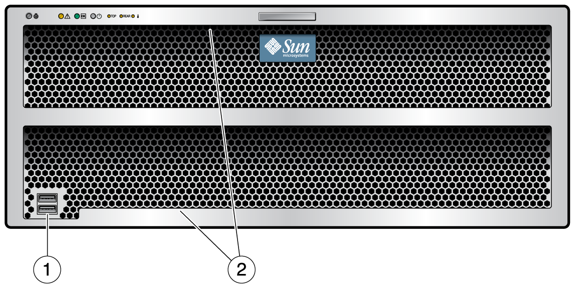
image:This graphic shows the front panel of the Sun Storage J4500 Array.

Figure Legend

1 USB ports—Not used

2 Serial numbers on ledge

Figure 1-2 Front Panel Controls and Indicators
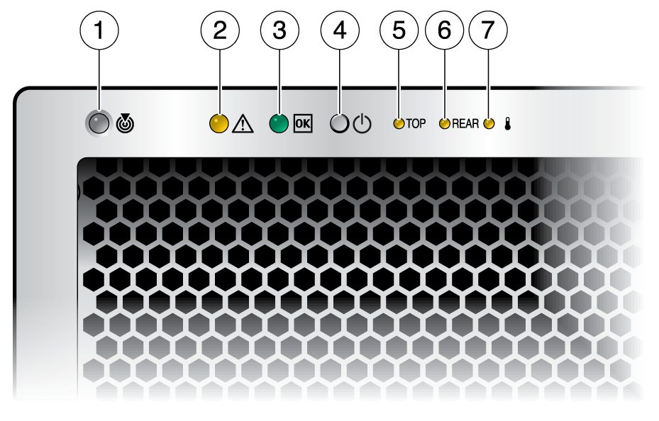
image:This graphic shows the front panel controls for the Sun Storage J4500 Array.

Table 1-2 Front Panel Controls and Indicators

#
Name
Description
1
Locate button/LED
Using array management software, operators can turn this LED on remotely to help them to locate the server in a crowded server room. Press to turn off.
2
System fault
On – Service action is required.
3
Power LED
On – Power is on. Blinking – Standby power is on but main power is off. Off – Power is off.
4
System power button
5
Top fault LED
On – Hard disk or fan fault.
6
Rear fault LED
On – Power supply, or system controller fault (service is required).
7
Over temperature LED
On – The enclosure has exceeded the operating temperature.

1.2.2 Back Panel

Sun Storage J4500 Array Back Panel shows the features of the back panel. Back Panel Features lists and describes each feature.

Figure 1-3 Sun Storage J4500 Array Back Panel
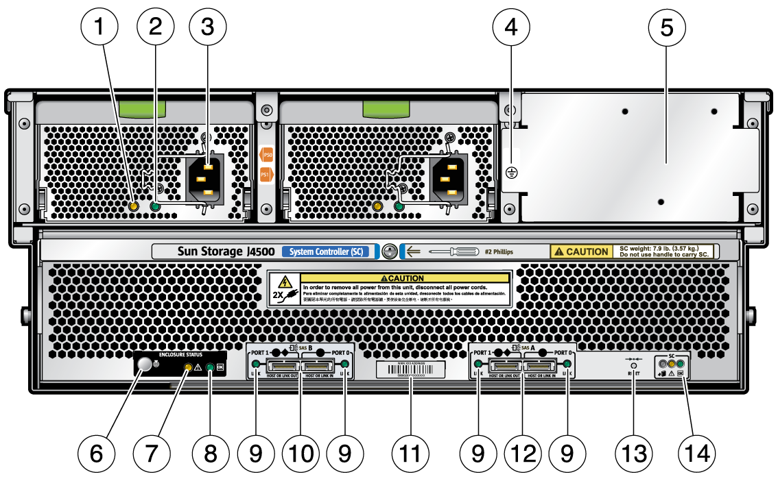
image:This graphic shows the back panel components of the Sun Storage J4500 Array.

Table 1-3 Back Panel Features

#
Name
Description
1
Power supply fault LED (amber)
On – Service action is required.
2
Power supply LED (green)
On – Power is on (AC/DC are OK). Blinking – Standby power is on (AC is OK). Off – Power is off.
3
AC power connector
Each power supply has its own AC connector with a clip to secure its power cable.
4
Chassis ground
Connect grounding straps here.
5
Filler panel
This filler panel seals an access area in the chassis used by service personnel.
6
Locate button/LED (white)
Using array management software, operators can turn this LED on remotely to help them to locate the enclosure in a crowded server room. Press to turn off.
7
System fault LED (amber)
On – Service action is required.
8
System power LED (green)
On – Power is on. Blinking – Standby power is on but main power is off. Off – Power is off.
9
SAS link activity LED (green)
Each SAS port has a SAS Link Activity LED:

On – 1 to 4 links are ready. Blinking – Read/Write port activity. Off – Link is lost.

10
Two mini-SAS x4 connector ports (SAS B)
Secondary (redundant) SAS ports 0 and 1, each with SAS Link activity LEDs. Port 0 uses subtractive or direct routing and connects to a host or upstream devices; Port 1 is universal, using table and direct routing, and connects to a host or downstream devices.
11
SAS ID (or WWN)
The label placed here lists the unique SAS ID address (also known as World-Wide Name) of the enclosure.
12
Two mini-SAS x4 connector ports (SAS A)
Primary SAS ports 0 and 1, each with SAS Link activity LEDs. Port 0 uses subtractive or direct routing and connects to a host or upstream devices; Port 1 is universal, using table and direct routing, and connects to a host or downstream devices.
13
Enclosure reset button
Resets the enclosure hardware without powering down the enclosure. For more information, see Chapter 4, Troubleshooting.
14
System controller status LEDs
Blue – Ready to remove (service action allowed)

Amber – Fault (Service action required)

Green – OK (no action required)

1.2.3 Sun Storage J4500 Array Internal Components

Internal Components shows the locations of the J4500 array components, with the covers removed. All power supplies, drives and fans are numbered and labeled.

Figure 1-4 Internal Components
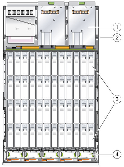
image:This graphic shows and lists the internal components of the Sun Storage J4500 Array.

Figure Legend

1 Power supplies (two: PS0 and PS1)

2 System Controller (SC) board (beneath power supplies)

3 Hard Disk Drives (48)

4 Fans (5 trays with two fans each)