| Skip Navigation Links | |
| Exit Print View | |

|
Sun Storage J4500 Array Service Manual |
1. Introduction to the Sun Storage J4500 Array
1.2 Exterior Features, Controls, and Indicators
1.2.3 Sun Storage J4500 Array Internal Components
2. Configuring and Powering On the Sun Storage J4500 Array
2.1.3 Cabling the SAS Connectors
2.2 Powering On and Off the Array
To Place the Array Into Standby Power Mode
2.2.1 AC Power Failure Auto-Recovery
3. Maintaining the Sun Storage J4500 Array
3.1 Options and Replaceable Components
3.4 Removing and Replacing the Hard Disk Drive Access Cover
To Remove the Hard Disk Drive Access Cover
To Replace the Hard Disk Drive Access Cover
3.5 Internal Component Locations
To Replace the Front Indicator Board
To Replace the Power Distribution Board
To Replace the System Controller Module
3.7 Upgrading Enclosure Firmware
3.7.1 Ensure Both SAS Fabrics are Upgraded to the Same Firmware Revision Level
4.2 Internal Disk Drive and Fan LEDs
4.3 Diagnostic and Management Tools
4.3.2 Common Array Manager (CAM)
4.4 Troubleshooting Problems with the Array
4.4.2 Check the Event and Performance Logs
4.4.3 Using the Array Management Software to Monitor Enclosure Health
4.4.6 Array Environment Problems
4.5 Resetting the Enclosure Hardware
To Reset the Enclosure Hardware Using the Reset Button
4.6 Clearing the Enclosure Zoning Password
To Clear the Enclosure Zoning Password
B.2 I/O-to-Disk Backplane Connectors
B.2.2 High-Speed Dock Connectors
B.4 Disk Backplane-to-Front Indicator Connector
Use the procedures in this section when you are referred to them from the removal and replacement procedures.
Before attempting to work inside the array enclosure, power it down as follows:
 | Caution - When you use the Power button to enter standby power mode, power is still directed to the power supply fans, indicated when the Power/OK LED is flashing. To completely power off the array enclosure, you must disconnect the AC power cords from the back panel of the array. |
It is a good idea to label your cables as you disconnect them to ensure correct reconnection.
 | Caution - Before handling components, attach an electrostatic discharge (ESD) wrist strap to a grounding point on the chassis. The system's printed circuit boards and hard disk drives contain components that are extremely sensitive to static electricity. |
This procedure assumes you have turned off the system and removed any cables or cords that would restrict the movement of the system.
 | Caution - To avoid serious personal injury and/or equipment damage while handling or moving this product, always use all four chassis handles to support the product weight. These systems can weigh up to 170 pounds (77 kg) when fully loaded with components. If only three people are available, remove power supplies, hard disks, and system controller to reduce the weight to about 50 pounds before removing the system. Leave the fan trays installed. Attempting this procedure without a mechanical lift or with fewer than four people could result in personal injury or equipment damage. |
To remove power supplies, see To Replace a Power Supply.
To remove the System Controller, see To Replace the System Controller Module.
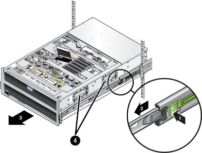
 | Caution - Once components have been removed, do NOT attempt to lift the chassis at these openings, the sheet metal may deform. Use the lifting handles on the sides of the chassis (see “4” in Removing the Enclosure from the Rack). |
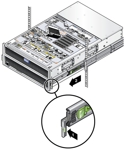
Figure 3-1 Sliding the Enclosure Out of the Rack

See To Remove the Hard Disk Drive Access Cover.
 | Caution - Make sure you label the drives so you can replace them in their original locations. Not doing so may result in data loss. |
Figure 3-2 Removing the Enclosure from the Rack

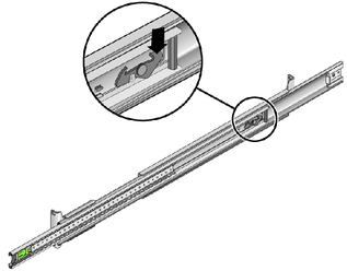
Figure 3-3 Releasing the Middle Rail Lock

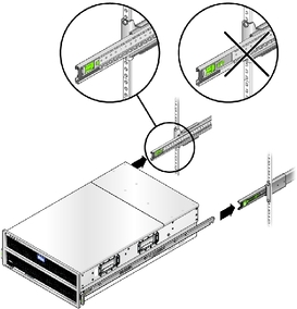
Note - When reinstalling the system into the rack, first pull the middle rails back out to their locking position (see Correct Setup for Inserting the System Into the Slide Rails) before attempting to reinsert the inner rails on the system into the middle and outer slide rails.
Figure 3-4 Correct Setup for Inserting the System Into the Slide Rails
