| Skip Navigation Links | |
| Exit Print View | |

|
Sun Storage J4500 Array Service Manual |
1. Introduction to the Sun Storage J4500 Array
1.2 Exterior Features, Controls, and Indicators
1.2.3 Sun Storage J4500 Array Internal Components
2. Configuring and Powering On the Sun Storage J4500 Array
2.1.3 Cabling the SAS Connectors
2.2 Powering On and Off the Array
To Place the Array Into Standby Power Mode
2.2.1 AC Power Failure Auto-Recovery
3. Maintaining the Sun Storage J4500 Array
3.1 Options and Replaceable Components
3.3 Powering Off the Array and Removing It From the Rack
To Remove the Array Enclosure From the Rack
3.4 Removing and Replacing the Hard Disk Drive Access Cover
3.5 Internal Component Locations
To Replace the Front Indicator Board
To Replace the Power Distribution Board
To Replace the System Controller Module
3.7 Upgrading Enclosure Firmware
3.7.1 Ensure Both SAS Fabrics are Upgraded to the Same Firmware Revision Level
4.2 Internal Disk Drive and Fan LEDs
4.3 Diagnostic and Management Tools
4.3.2 Common Array Manager (CAM)
4.4 Troubleshooting Problems with the Array
4.4.2 Check the Event and Performance Logs
4.4.3 Using the Array Management Software to Monitor Enclosure Health
4.4.6 Array Environment Problems
4.5 Resetting the Enclosure Hardware
To Reset the Enclosure Hardware Using the Reset Button
4.6 Clearing the Enclosure Zoning Password
To Clear the Enclosure Zoning Password
B.2 I/O-to-Disk Backplane Connectors
B.2.2 High-Speed Dock Connectors
B.4 Disk Backplane-to-Front Indicator Connector
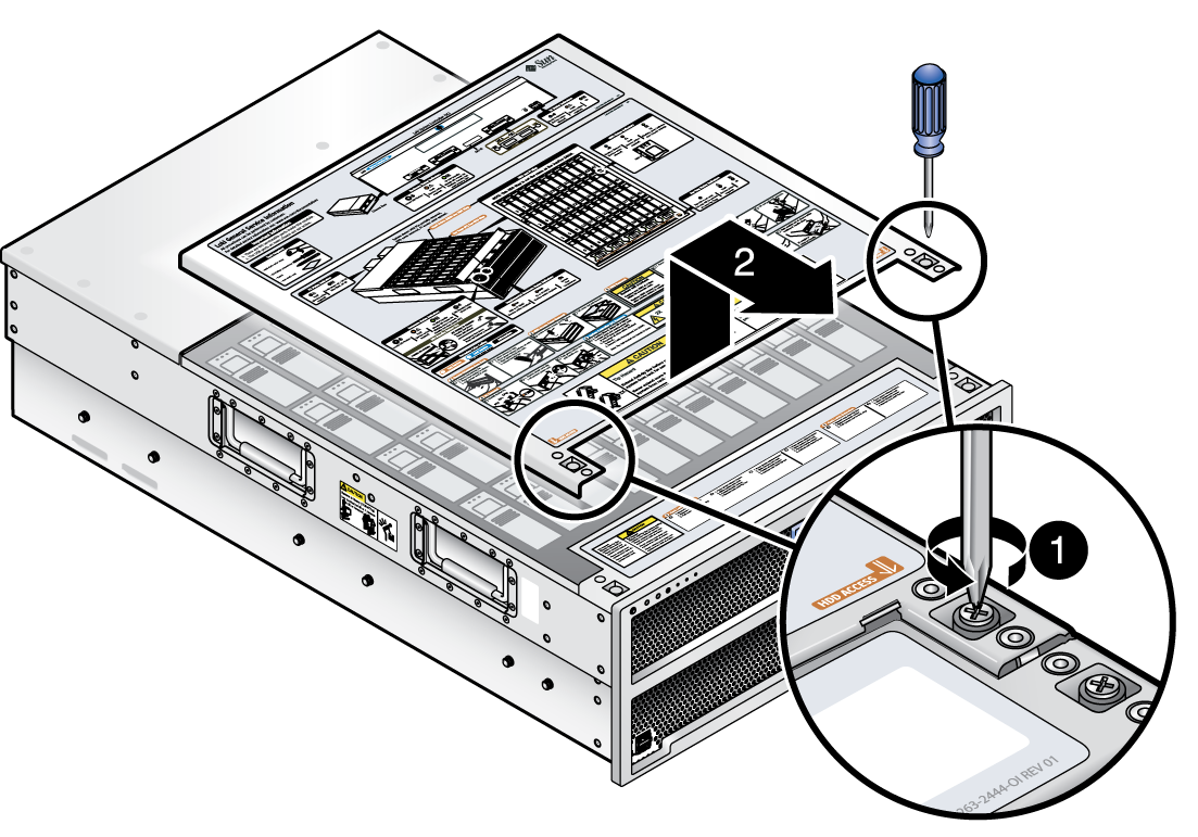
This section describes how to remove and replace the array enclosure hard disk drive access cover.
The hard disk drive access cover protects the 48 hard disks in the array enclosure and ensures proper cooling to the drives and the system controller.
 | Caution - When the array is powered on, the hard disk drive access cover should be in place to ensure proper cooling. Do not remove the cover for more than 60 seconds when the array power is on. |
Figure 3-5 Removing the Hard Disk Drive Access Cover

Complete the following steps to replace the hard disk drive access cover.
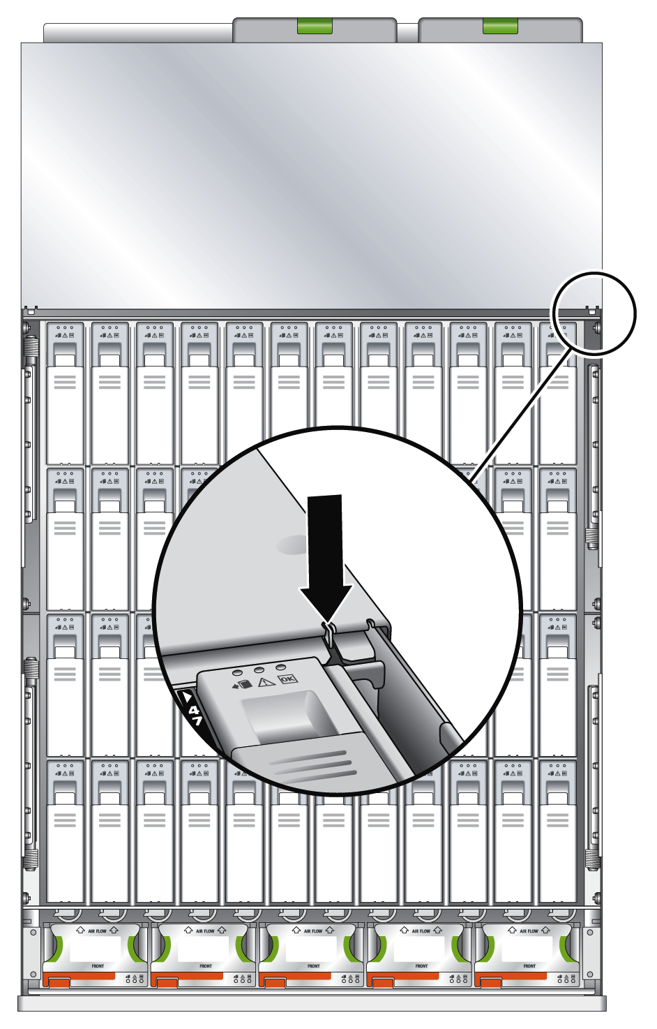
 | Caution - Be careful not to damage the hard disk drive access cover intrusion switch when you replace the cover. See Hard Disk Drive Access Cover Intrusion Switch. |
Figure 3-6 Hard Disk Drive Access Cover Intrusion Switch
