| Skip Navigation Links | |
| Exit Print View | |

|
Sun Storage J4500 Array Service Manual |
1. Introduction to the Sun Storage J4500 Array
1.2 Exterior Features, Controls, and Indicators
1.2.3 Sun Storage J4500 Array Internal Components
2. Configuring and Powering On the Sun Storage J4500 Array
2.1.3 Cabling the SAS Connectors
2.2 Powering On and Off the Array
To Place the Array Into Standby Power Mode
2.2.1 AC Power Failure Auto-Recovery
3. Maintaining the Sun Storage J4500 Array
3.1 Options and Replaceable Components
3.3 Powering Off the Array and Removing It From the Rack
To Remove the Array Enclosure From the Rack
3.4 Removing and Replacing the Hard Disk Drive Access Cover
To Remove the Hard Disk Drive Access Cover
To Replace the Hard Disk Drive Access Cover
3.5 Internal Component Locations
To Replace the Front Indicator Board
To Replace the Power Distribution Board
3.7 Upgrading Enclosure Firmware
3.7.1 Ensure Both SAS Fabrics are Upgraded to the Same Firmware Revision Level
4.2 Internal Disk Drive and Fan LEDs
4.3 Diagnostic and Management Tools
4.3.2 Common Array Manager (CAM)
4.4 Troubleshooting Problems with the Array
4.4.2 Check the Event and Performance Logs
4.4.3 Using the Array Management Software to Monitor Enclosure Health
4.4.6 Array Environment Problems
4.5 Resetting the Enclosure Hardware
To Reset the Enclosure Hardware Using the Reset Button
4.6 Clearing the Enclosure Zoning Password
To Clear the Enclosure Zoning Password
B.2 I/O-to-Disk Backplane Connectors
B.2.2 High-Speed Dock Connectors
B.4 Disk Backplane-to-Front Indicator Connector
This section provides procedures replacing enclosure components. All of the components described here are customer-replaceable units (CRUs).
This section describes the following replacement tasks:
 | Caution - Before handling components, attach an ESD wrist strap to a grounding location on the chassis (see Sun Storage J4500 Array Internal Components). The enclosure's printed circuit boards and hard disk drives contain components that are extremely sensitive to static electricity. |
Each fan module (also known as a fan tray) has two fans. The array enclosure has five fan modules (for a total of 10 fans in the enclosure). This component is customer replaceable.
Note - Enclosure cooling might be affected by dust and contaminant build-up. It is recommended that the enclosure be opened and checked approximately every six months or more often in dirty operating environments. Check component heatsinks, fans, and air openings. If necessary, clean the enclosure by brushing or blowing contaminants or carefully vacuuming contaminants from the enclosure.
Fans are labeled FT0 (fan tray 0) to FT4 (fan tray 4). See 3.5 Internal Component Locations.
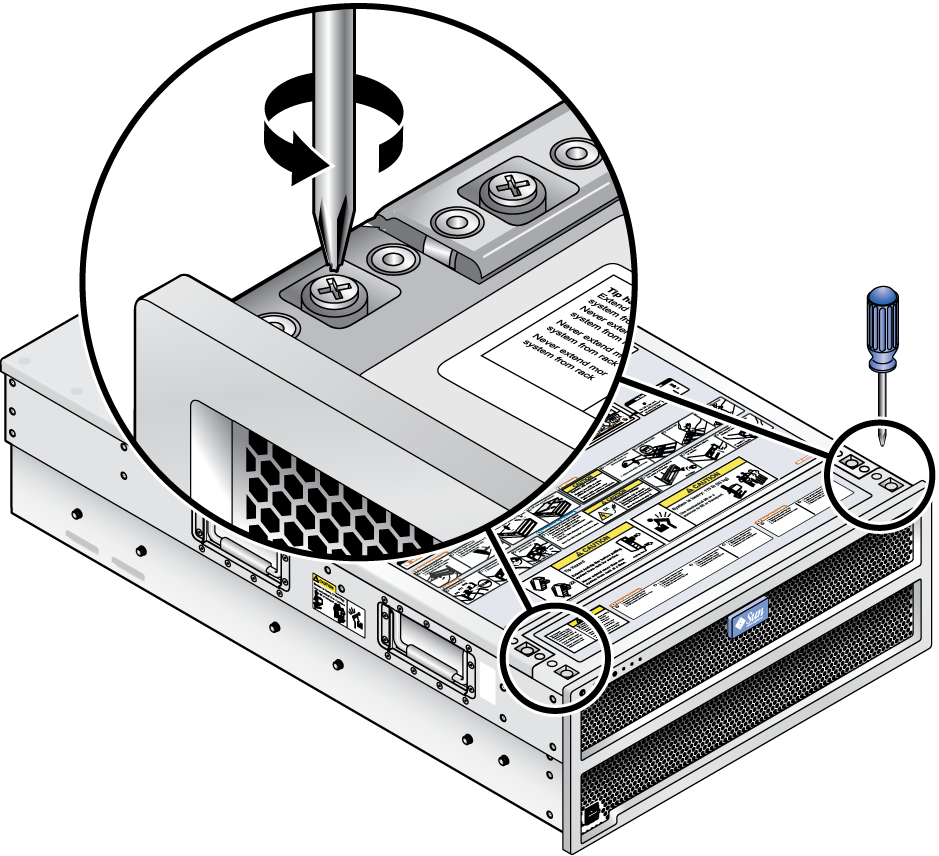
Using a No. 2 Phillips screwdriver, loosen the two captive screws on the left and right sides. See Removing the Fan Tray Cover.
Figure 3-8 Removing the Fan Tray Cover
If the amber (left) LED is on, the fan module is defective and should be replaced.
Note - If both green and amber indicators are on, then one of the two fans in the fan module is still operational. You should replace this fan module last if there is more than one fan module failure.
 | Caution - Be careful to not damage the gaskets when you remove the fan module. Damaging the gaskets can disrupt proper airflow. |
Using your thumb and forefinger, grasp the top handle of the fan module and lift the module up and out of the chassis. See Removing a Fan Module.
Figure 3-9 Removing a Fan Module
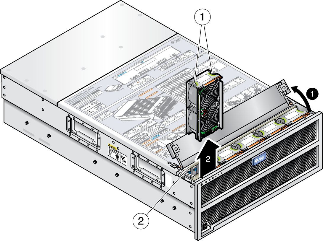
Figure Legend
1 Grab fan tray module by finger handle
2 Be careful not to damage the enclosure fan tray module gaskets
The front indicator board supports the front panel power button and front panel indicator LEDs. This board also contains the ribbon cable that connects to the hard disk drive backplane. Be sure you have the tools necessary as described in 3.2 Tools and Supplies Needed.
 | Caution - To power off the enclosure completely, you must disconnect the AC power cords from the back panel of the array enclosure. It takes a full 20 seconds with the AC power cords unplugged for internal power to be completely drained from the enclosure. |
Using a No. 2 Phillips screwdriver, loosen the two captive screws on the left and right sides.
Using a No. 2 Phillips screwdriver, loosen the two captive screws on the left and right sides.
Figure 3-10 Removing the Front Indicator Board Screws
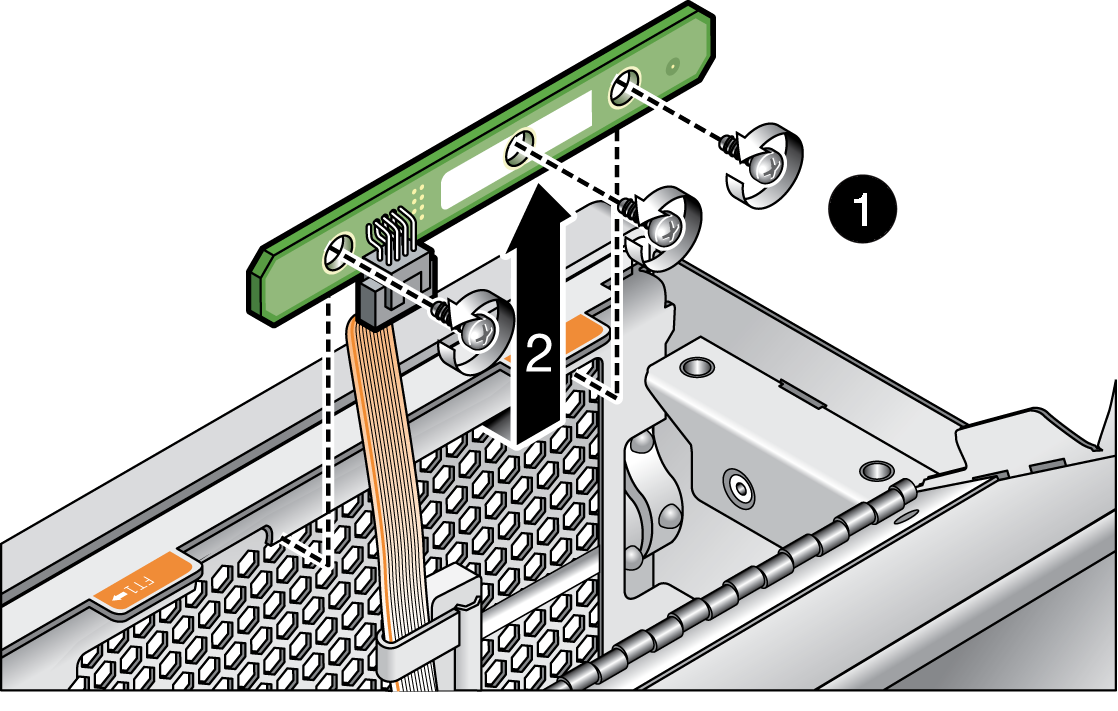
If you suspect that the ribbon cable is bad, remove the old ribbon cable from the hard disk drive backplane and use the new ribbon cable that comes with the new front indicator board. Make sure you route the ribbon cable through the cable securing clips to prevent damage to the cable.
Figure 3-11 Detaching the Ribbon Cable from the Hard Disk Backplane
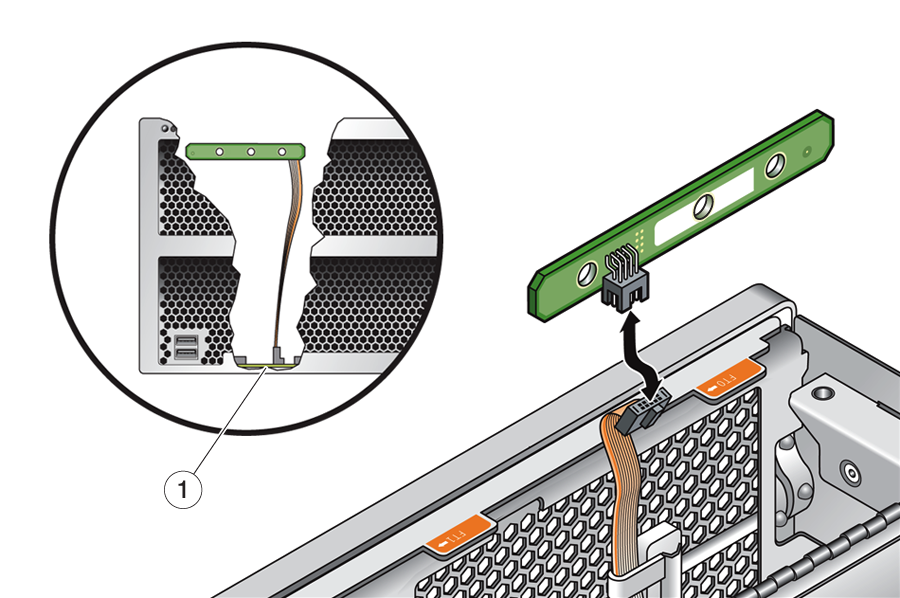
Figure Legend
1 Ribbon cable connection to hard disk backplane
This section describes how to remove and replace a hard disk drive. The J4500 array comes fully populated with 48 SATA drives installed. When replacing drives, note the following:
Replacement drives must be SATA, of the same capacity, and the same manufacturer as the drive being replaced. If is configured for multipathing, only supported drives may be used (for more on drives supported for multipath, see 4.4.5.4 Multipath Problems With Unsupported Drives).
Drives are a hot-pluggable CRU and can be replaced by anyone. Hot-pluggable means that the hard drive must be first brought offline by using a management software or operating system command; however, the array does not need to be powered off.
A single hard disk failure does not cause data loss if the hard disk is part of a RAID 1 (or higher) volume. The hard disk can be hot-plugged (but not hot-swapped). When a new hard disk is inserted, the contents are automatically rebuilt from the rest of the array with no need to reconfigure the RAID parameters. If the bad hard disk was configured as a hot spare, the new hard disk is automatically configured as a new hot spare.
Do not configure RAID volumes with drives of different capacities. This can cause unexpected operation or other problems. All drives in the array enclosure must be SATA and of the same capacity.
Each hard disk has a physical drive number, a map of the array hard disks is shown on the service label.
When using Linux hosts, if you add or remove array disks the host might hang or panic due to known Linux kernel issues. If you encounter this problem, a reboot of the host should resolve it.
 | Caution - To avoid overheating the array enclosure, do not leave a hard disk drive out for longer than 60 seconds at a time when the array power is on. Remove and replace only one hard disk drive at a time. Replace the hard disk drive access cover as soon as the service tasks are completed. |
If the amber (middle) LED is on, the drive is faulty and should be replaced.
 | Caution - Taking a disk offline that is part of a non-redundant logical drive causes the entire logical drive to fail and result in data loss. |
If you are using an operating system command line, note that disks in the enclosure are typically identified in sequential order. Although the enclosure contains only 48 disks, your operating system may see a list of 51 devices; if this is the case, the first 4 addresses (0-3) represent the enclosure's four SAS expanders, the other 48 addresses (4-51) represent the 48 hard disks.
Once the drive has been taken off line, the blue ready-to-remove LED should turn on. This means the drive is ready to be removed and service action is allowed.
Lift the metal latch and remove the hard disk from the drive bay as shown in Removing a Hard Disk Drive, or on the service label.
Figure 3-12 Removing a Hard Disk Drive
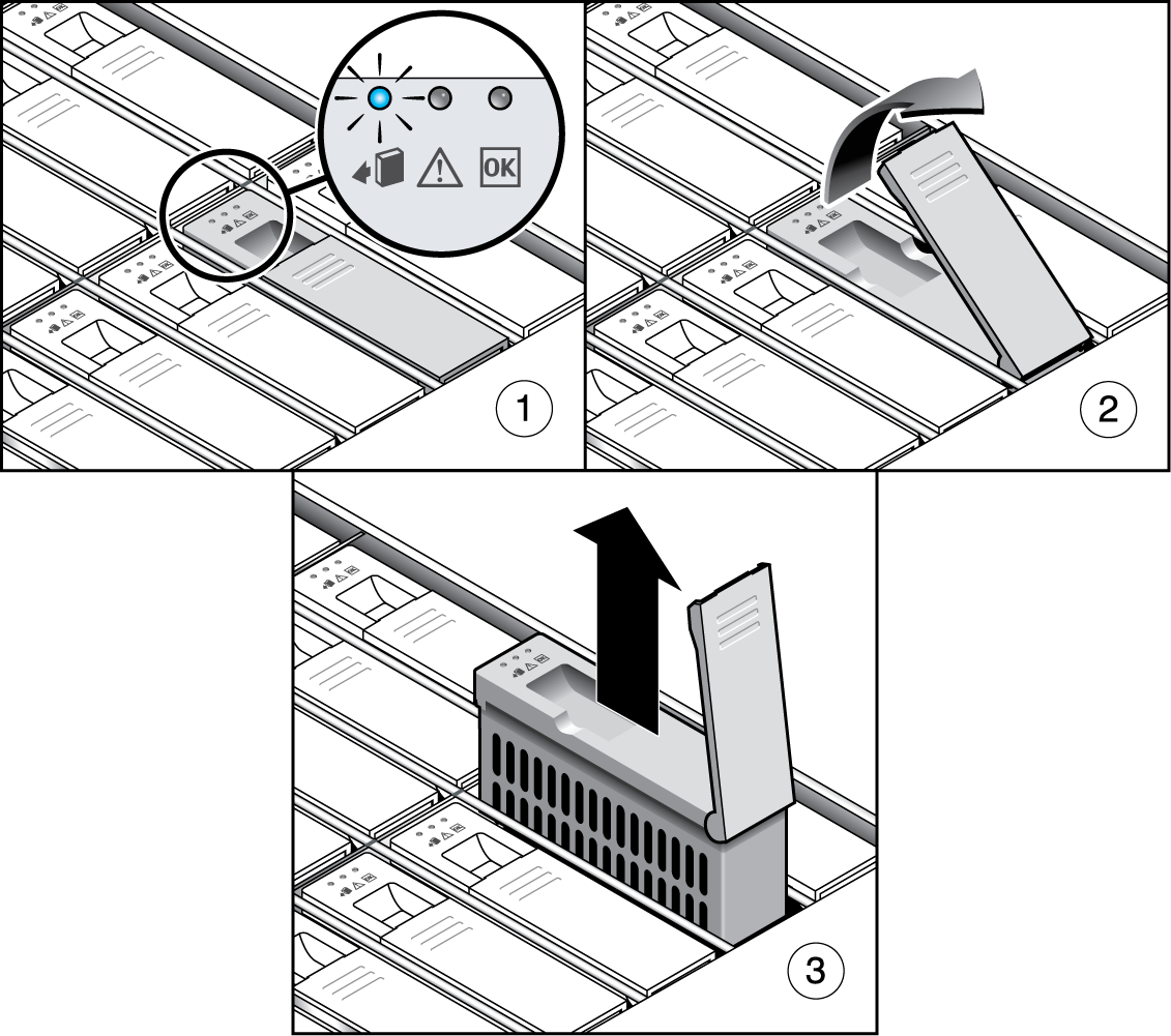
Figure Legend
1 Identify desired hard disk
2 Unlatch hard disk
3 Lift and pull hard disk up and out of bay
Push the hard disk into the bay until it stops, and make sure the drive is fully engaged with the connector on the hard disk backplane.
Refer to your HBA or operating system documentation for information on adding a new hard disk.
Note - If the hard disk was previously configured as a RAID 1 (or higher) array, an automatic resynchronization is invoked and the contents are automatically rebuilt from the rest of the array with no need to reconfigure the RAID parameters. If the bad hard disk was configured as a spare, the new hard disk is automatically configured as a new spare.
This section describes how to remove and replace the power distribution board (PDB), which is also called the power backplane. Be sure you have the tools necessary as described in 3.2 Tools and Supplies Needed.
 | Caution - To power off the enclosure completely, you must disconnect the AC power cords from the back panel of the array enclosure. It takes a full 20 seconds with the AC power cords unplugged for internal power to be completely drained from the enclosure. |
Using a No. 1 Phillips screwdriver, remove the two screws on the power supply cover. Pull the cover toward you and lift. Some extra effort may be required to disengage the eight mushroom-head pins that secure the power supply cover to the chassis (see Removing the Power Supply Area Cover).
Figure 3-13 Removing the Power Supply Area Cover
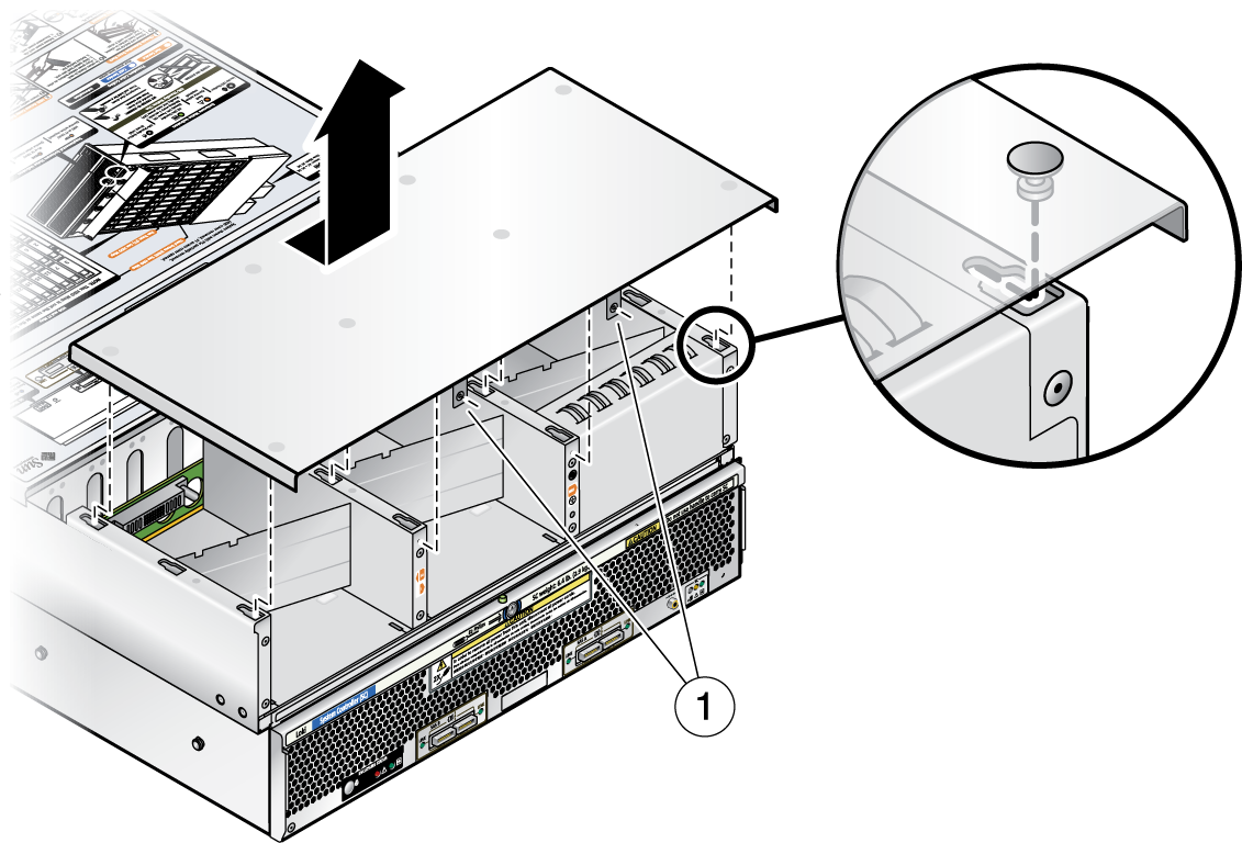
Figure Legend
1 Power supply cover securing screws
You must remove the rear chassis filler panel to get access to one of the screws that attaches the PDB to the chassis.
Figure 3-14 Removing the Rear Chassis Filler Panel
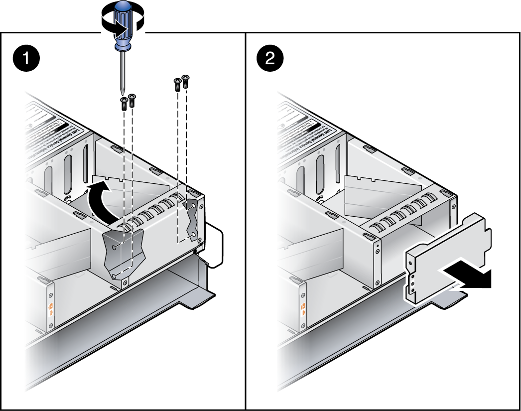
Figure 3-15 Removing the Power Distribution Board
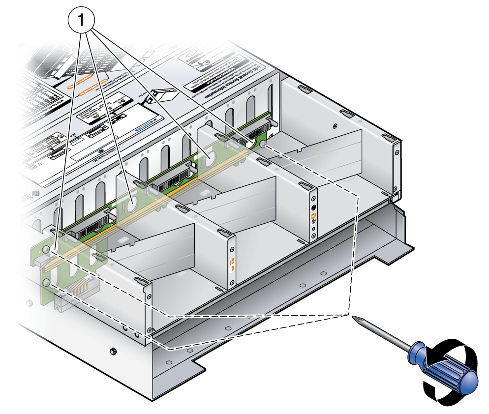
Figure Legend
1 Power Distribution Board (PDB) securing screws
Figure 3-16 Pulling Out the Power Distribution Board
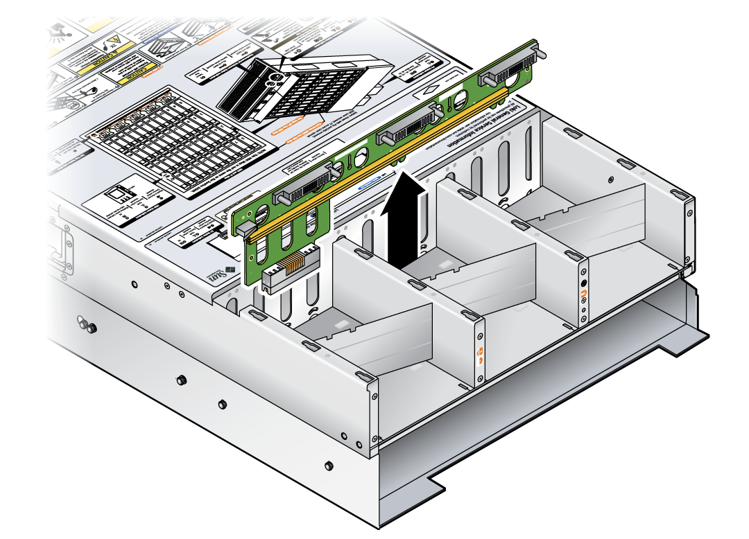
This section describes how to remove and replace a power supply.
The power supplies are fully redundant from 110 to 220 VAC; if one power supply fails, the other power supply will continue to operate.
Note - This component is a hot-swappable CRU and can be replaced by anyone. Hot-swappable means that you do not need to power off the array during replacement. However, you must unplug the power supply to be replaced or the entire system could shut down during removal.
The physical numbering of the two power supplies in the array enclosure is shown on the service label.
The power supplies are hot-swappable, so you do not have to shut down the array or disconnect AC power from the other working power supply.
Note - The Service Action Required LEDs on the front panel and back panel blink when a power supply is unplugged. See 4.1 External Status LEDs for the LED locations and descriptions.
Figure 3-17 x86: Removing a Power Supply
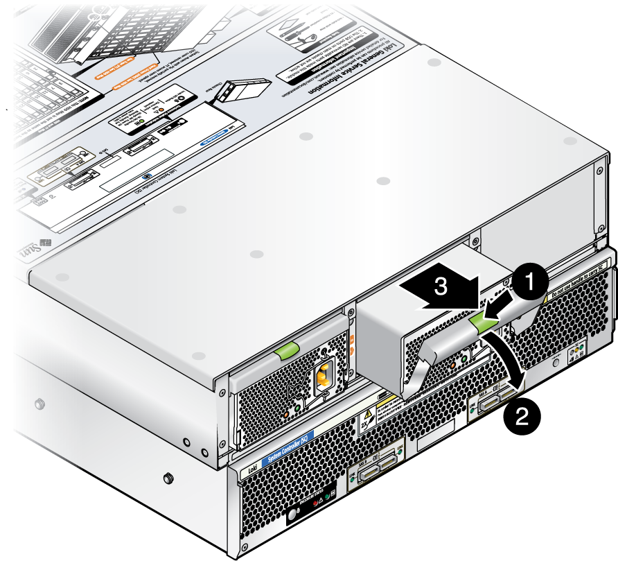
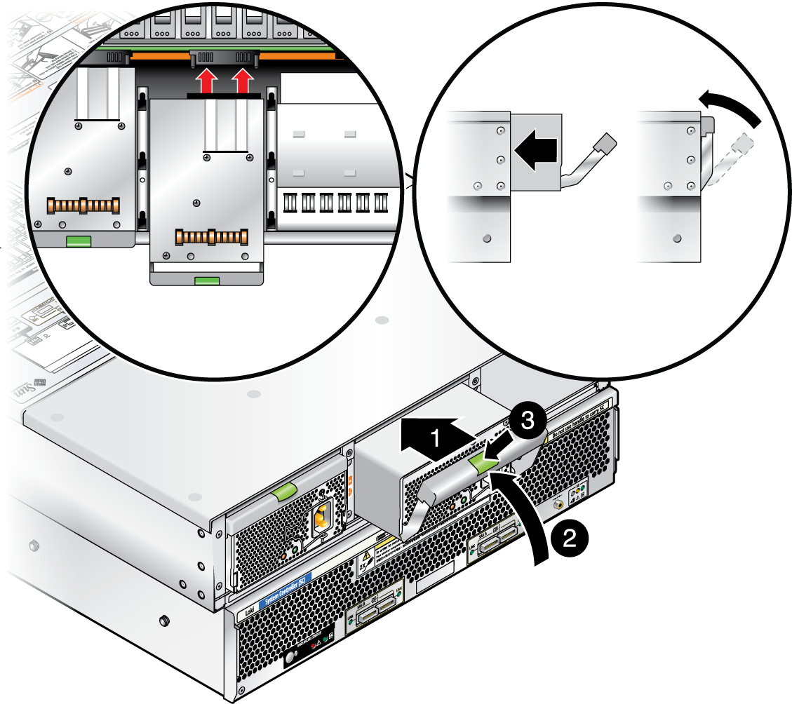
Figure 3-18 x86: Replacing a Power Supply
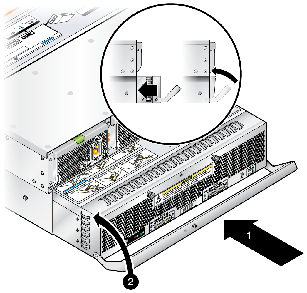
The system controller (SC) consists of a sub-enclosure module and board that are removed as a unit from the back of the array enclosure. The system controller board contains the SAS expanders used to access the enclosure's 48 hard disk drives. The module is replaced as a unit—there are no replaceable parts inside.
Note the following before you begin:
If the array was configured for zoning (array storage divided among multiple initiators), ensure that the zoning configurations created with the Sun Comman Array Manager (version 6.4.1 at a minimum) have been exported to a file. Zoning configurations (including initiator-to-disk access and SAS domain passwords) are saved on the array's SAS expanders in the SC. You will need to import these configurations (per initiator and SAS domain) after you replace the SC. Refer to the chapters on zoning and multipathing in the Sun Storage J4500 Array System Overview (820-3163) for proper initiator-to-disk access configuration.
Be sure that you have first taken the array offline to prevent any host computer processes attempting to accessing it while the system controller is removed.
Be aware of SATA affiliations. When SATA drives are used, an affiliation (dedication) to the initiator (HBA port) is automatically created. This complies with the SATA protocol and is point-to-point in nature. If multiple initiators are attached to a single SAS fabric (either SAS A or B), the drive-to-initiator affiliation will be arbitrarily chosen which can create potential issues (such as disks or initiators not being seen). Refer to the chapters on zoning and multipathing in the Sun Storage J4500 Array System Overview (820-3163) for proper initiator-to-disk access configuration. Also refer to the Sun StorageTek Common Array Manager Release Notes for the version of CAM being used.
 | Caution - To prevent electrostatic discharge (ESD) damage to the components on the system controller, connect a ground strap between yourself and the chassis ground before proceeding. See Sun Storage J4500 Array Internal Components. |
 | Caution - Although both power supplies should turn off when you remove the system controller, voltage could be present on the chassis connectors if either power supply did not shut down as expected. Thus, you must disconnect the power cords from the power supplies and wait 20 seconds to avoid any risk from inadvertent contact with those connectors. |
You must label where your cables are connected as you disconnect them to ensure correct reconnection to a supported configuration.
Figure 3-19 x86: Removing the SC Module
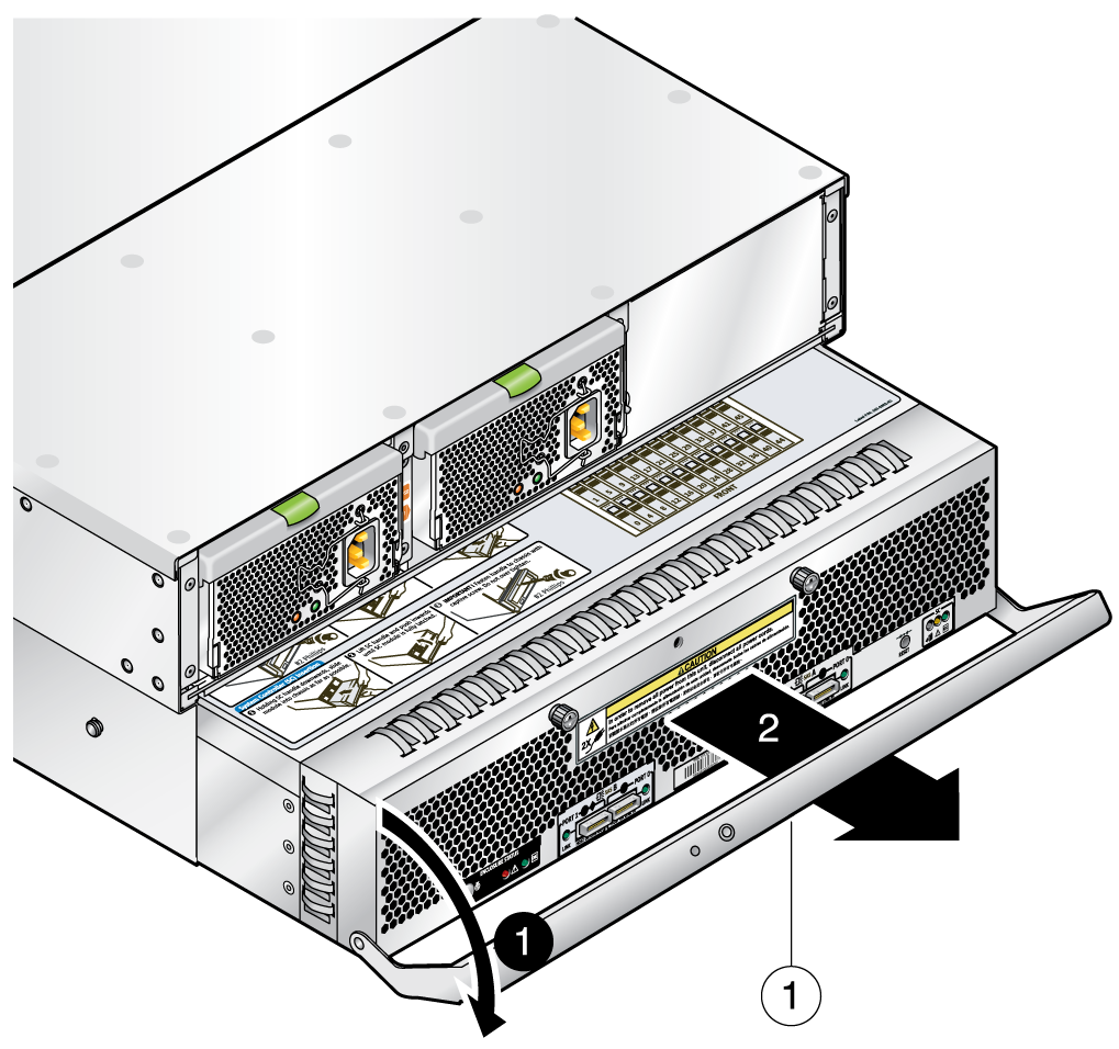
Figure Legend
1 System Controller (SC) handle lock screw location
Note that the SC module is connected inside the enclosure to the power distribution board, you may need to exert some pressure to disengage it.
 | Caution - The module will not plug into the power distribution board with the connector covers on. |
As the module engages the power distribution board, the module handle will lift into place.
Figure 3-20 Replacing the SC Module
Detailed instructions for configuring zoning and multipathing for the array can be found in the Sun Storage J4500 Array System Overview (820-3163) and the Sun StorageTek Common Array Manager Release Notes for the version of CAM being used.
This section describes how to replace the array chassis, which includes the chassis, the hard disk drive backplane, and the front indicator board and ribbon cable.
Note - When you remove the hard disks from their bays, you must return each hard disk to the equivalent bay in the new chassis. Use an adhesive note or another method to temporarily label the hard disks before you remove them.
Note - You must return each hard disk to the bay from which it was removed. If the hard disks were previously configured for RAID (level 1 or higher), an automatic resynchronization should be invoked after the initial power on of the new enclosure to reconfigure the RAID parameters. Any hot spares should also be automatically reconfigured as hot spares.