| Skip Navigation Links | |
| Exit Print View | |

|
Sun Storage J4500 Array Service Manual |
1. Introduction to the Sun Storage J4500 Array
1.2 Exterior Features, Controls, and Indicators
1.2.3 Sun Storage J4500 Array Internal Components
2. Configuring and Powering On the Sun Storage J4500 Array
2.1.3 Cabling the SAS Connectors
2.2 Powering On and Off the Array
To Place the Array Into Standby Power Mode
2.2.1 AC Power Failure Auto-Recovery
3. Maintaining the Sun Storage J4500 Array
3.1 Options and Replaceable Components
3.3 Powering Off the Array and Removing It From the Rack
To Remove the Array Enclosure From the Rack
3.4 Removing and Replacing the Hard Disk Drive Access Cover
To Remove the Hard Disk Drive Access Cover
To Replace the Hard Disk Drive Access Cover
3.5 Internal Component Locations
To Replace the Front Indicator Board
To Replace the Power Distribution Board
To Replace the System Controller Module
3.7 Upgrading Enclosure Firmware
3.7.1 Ensure Both SAS Fabrics are Upgraded to the Same Firmware Revision Level
4.2 Internal Disk Drive and Fan LEDs
4.3 Diagnostic and Management Tools
4.3.2 Common Array Manager (CAM)
4.4 Troubleshooting Problems with the Array
4.4.2 Check the Event and Performance Logs
4.4.3 Using the Array Management Software to Monitor Enclosure Health
4.4.6 Array Environment Problems
4.5 Resetting the Enclosure Hardware
To Reset the Enclosure Hardware Using the Reset Button
4.6 Clearing the Enclosure Zoning Password
To Clear the Enclosure Zoning Password
B.2 I/O-to-Disk Backplane Connectors
B.2.2 High-Speed Dock Connectors
B.4 Disk Backplane-to-Front Indicator Connector
This appendix contains physical, power, environmental, acoustic noise emission and disk mapping specifications for the Sun Storage J4500 array.
Table A-1 Sun Storage J4500 Array Physical Specifications
|
Table A-2 Sun Storage J4500 Array Power Specifications
|
Table A-3 Sun Storage J4500 Array Environmental Specifications
|
Sun Storage J4500 Array Acoustic Noise Emission Specifications contains the declared noise emissions in accordance with ISO 9296, A-weighted, operating, and idling.
Table A-4 Sun Storage J4500 Array Acoustic Noise Emission Specifications
| ||||||||||||
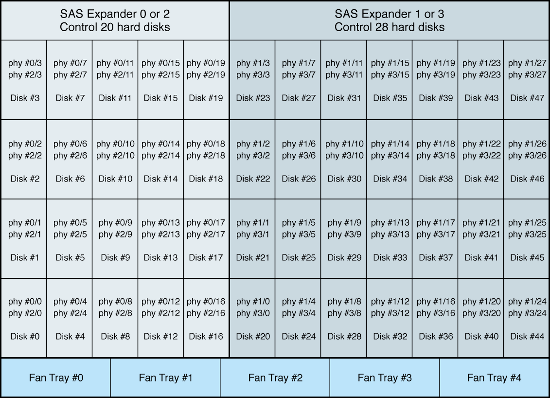
Hard Disk Drive Phy Map shows the hard disk numbering scheme. The hardware SATA port number is composite of two numbers, x/y, x is the expander's number (0-3), y is the expander's phy port number (0- 47). For example, 0/4 means expander 0/phy 4, each hard disk connected to two SATA phy ports through an active-active mux.
Figure A-1 Hard Disk Drive Phy Map
