| Skip Navigation Links | |
| Exit Print View | |

|
Sun Storage J4500 Array Service Manual |
1. Introduction to the Sun Storage J4500 Array
1.2 Exterior Features, Controls, and Indicators
1.2.3 Sun Storage J4500 Array Internal Components
2. Configuring and Powering On the Sun Storage J4500 Array
2.1.2.2 Connecting Host Bus Adapters (HBAs)
2.1.2.3 Connecting Multiple Sun Storage J4500 Arrays
2.1.2.5 Configuration with Blade Servers
2.1.3 Cabling the SAS Connectors
2.1.4.1 Single Host Direct Connection
2.1.4.2 Single Host With Cascaded Arrays
2.1.4.3 Single Host Direct Connection to Two Arrays
2.2 Powering On and Off the Array
To Place the Array Into Standby Power Mode
2.2.1 AC Power Failure Auto-Recovery
3. Maintaining the Sun Storage J4500 Array
3.1 Options and Replaceable Components
3.3 Powering Off the Array and Removing It From the Rack
To Remove the Array Enclosure From the Rack
3.4 Removing and Replacing the Hard Disk Drive Access Cover
To Remove the Hard Disk Drive Access Cover
To Replace the Hard Disk Drive Access Cover
3.5 Internal Component Locations
To Replace the Front Indicator Board
To Replace the Power Distribution Board
To Replace the System Controller Module
3.7 Upgrading Enclosure Firmware
3.7.1 Ensure Both SAS Fabrics are Upgraded to the Same Firmware Revision Level
4.2 Internal Disk Drive and Fan LEDs
4.3 Diagnostic and Management Tools
4.3.2 Common Array Manager (CAM)
4.4 Troubleshooting Problems with the Array
4.4.2 Check the Event and Performance Logs
4.4.3 Using the Array Management Software to Monitor Enclosure Health
4.4.6 Array Environment Problems
4.5 Resetting the Enclosure Hardware
To Reset the Enclosure Hardware Using the Reset Button
4.6 Clearing the Enclosure Zoning Password
To Clear the Enclosure Zoning Password
B.2 I/O-to-Disk Backplane Connectors
B.2.2 High-Speed Dock Connectors
B.4 Disk Backplane-to-Front Indicator Connector
The J4500 array can be connected to a supported HBA (Host Bus Adapter) installed in a server. The rules for connecting J4500 array are described here.
There are several terms used in this document that you will need to become familiar with to better understand J4500 array configuration options.
Table 2-1 Sun Storage J4500 Array Configuration Terms and Definitions
|
Before attaching cables to the J4500 array, read through the following configuration rules:
The array enclosure drive bays must be fully populated. All 48 SATA hard disk drives must be present and the same size. Do not mix drive capacities in the array enclosure; however you could, for example, have one J4500 populated with 750 GB SATA drives and a daisy-chained J4500 array with 1 TB SATA drives. The J4500 array does not support SAS drives.
The mini-SAS connector ports are configured as follows: Port 0 uses subtractive or direct routing (indicated by the circle icon above the connector, see Sun Storage Array Back Panel SAS Ports) and connects to upstream devices (either an HBA, or an upstream J4500 array). Port 1 is universal (indicated by the diamond and circle icons), using table and direct routing, and connects to either an upstream HBA or a downstream J4500 array.
Use only supported mini-SAS x4 cables (SFF-8088). There are two cables included with the array. Refer to 3.1 Options and Replaceable Components for additional cable options. Maximum cable lengths between devices is 6 meters. Using non-Sun certified cables or longer cables is not supported.
Do not cross connect an array enclosure's SAS fabrics. The SAS A ports of an array enclosure must not be cross connected to its SAS B ports.
 | Caution - Cross connecting the SAS fabrics of a J4500 array (connecting its SAS A ports to its SAS B ports) can cause the HBA to be unable to properly identify or access drives in the array which could lead to data loss. |
HBAs can be connected as follows:
Use only supported HBAs with the array. At initial release, supported HBAs for use with your array product are:
Sun StorageTek SAS RAID Eight-Port, External HBA (SG-XPCIESAS-R-EXT-Z, Adaptec™-based RAID controller). Single path configurations only.
Sun StorageTek PCI Express SAS 8-Channel External HBA (SG-XPCIE8SAS-E-Z, LSI™-based disk controller). Single or multipath configurations supported.
Sun StorageTek ExpressModule SAS 8-Channel External HBA (SG-PCIE8SAS-EB-Z, LSI-based disk controller). Single or multipath configurations supported.
An updated list of supported HBAs is maintained in the Sun Storage J4500 Array Product Notes (820-3162) available on the Sun documentation web site http://docs.sun.com.
A single path configuration consists of a single SAS cable connecting a single HBA to one of the array's SAS fabrics, either A or B.
A multipath configuration consists of connections to both of the J4500 array's SAS fabrics, A and B, using one or more HBAs in order to create a dual path. More on configuring your array for multipathing can be found in the Sun Storage J4500 Array System Overview (820-3163).
Configuring zoning of the array storage is currently only available using the Sun Common Array Manager (CAM) through an LSI-based HBA connected to the array. For more information on zoning, see the Sun Storage J4500 Array System Overview (820-3163).
Note - The J4500 array is not supported in a clustering configuration.
Sun Storage J4500 arrays can be daisy-chained, or cascaded, together as follows:
The maximum number of arrays that can be daisy-chained together is limited by the number of SAS targets (also called “devices” or “end devices”) supported by the attached HBA. Check the HBA's documentation to see how many SAS targets are supported. Also see 2.1.2.4 SAS Target Limits.
In single path configuration, arrays may be cascaded from Port 1 (out) of the upstream array to Port 0 (in) of the downstream array. Array cascade port connections must be of compatible types (for example, no array cascading from Port 1-to-1, Port 0-to-0, or Port 0-to1).
In a multipath configuration (creating a dual path by utilizing both SAS fabrics), Sun recommends cascading the host links in opposite directions from the edge of the SAS fabric. For example, the first host connection goes to the top of the SAS A fabric and cascades down, while the second host connection goes to the bottom of the SAS B fabric and cascades up. Array cascade port connections must be of compatible types (for example, no array cascading from Port 1-to-1 or Port 0-to-0). For more on configuring for multipathing, see the Sun Storage J4500 Array System Overview (820-3163).
Do not mix a J4500 array with any other type of JBOD array in a daisy-chain. Check the Sun Storage J4500 Array System Overview (820-3163) for updated configuration information.
To ensure a given configuration of J4500 array's does not exceed the HBAs' target limit, the following rules apply:
For single path configurations, each hard disk visible to an HBA consumes one target.
For multipath configurations, each hard disk visible to an HBA consumes two targets.
Each expander visible to an HBA consumes three targets. There are two expanders per SAS fabric in the array.
When zoning is being used on array storage, there must be a host that runs the zoning manager. This host must be able to communicate with all targets in the system. This means that the number of targets seen by the zoning host's HBA(s) must not exceed the target limit for that HBA.
Refer to your HBA documentation to find out how many targets it can support. Targets might also be called “devices” or “end devices.”
For Sun Blade Server Modules, the same configuration rules listed above for Sun Storage J4500 arrays apply with the following blade-specific rules:
An array may be connected to a Sun Blade Server Module in single path or multipath configuration using a supported SAS PCIe ExpressModule HBA that includes SAS x4-wide connectors. An updated list of supported HBAs are maintained in the Sun Storage J4500 Array Product Notes (820-3162) available on the Sun documentation web site.
The array may not be connected to a SAS NEM in the chassis (a Network Expansion Module that includes external SAS connectors). A server blade may also have its own set of drives and expanders, or be connected to a storage blade and already be using the SAS NEM. This can limit the number of available SAS targets supported by the blade server's internal HBA. Therefore, the J4500 array should only be connected to a supported SAS PCIe ExpressModule HBA that is used exclusively to connect external SAS devices.
The following figure shows the SAS connector ports for cabling J4500 array to your server's HBA. Before cabling a J4500 array to your server's HBA, refer to the 2.1 Configuration and Cabling.
Figure 2-1 x86: Sun Storage Array Back Panel SAS Ports

Figure Legend
1 SAS B (secondary fabric)
2 SAS A (primary fabric)
The J4500 array has two SAS fabrics: SAS A (primary) and SAS B (secondary). Each connector port on both fabrics connects to all 48 disks. SAS B is a redundant fabric. SAS port descriptions and assignments are shown in SAS Ports (Diagram Applies to Both SAS A Ports and SAS B Ports) .
Examples of supported configurations can be found in 2.1.4 Example Configurations.
Figure 2-2 x86: SAS Ports (Diagram Applies to Both SAS A Ports and SAS B Ports)
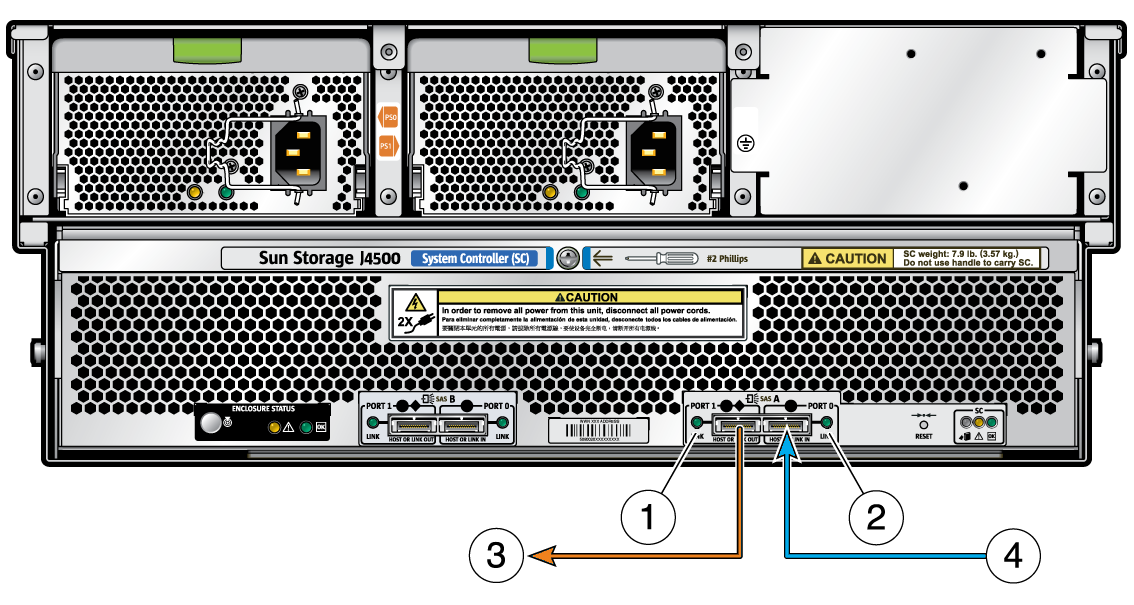
Figure Legend
1 SAS Port 1 (4 PHYs, activity LED, supports direct or table routing)
2 SAS Port 0 (4 PHYs, activity LED, supports direct or subtractive routing)
3 Port 1 connects to an HBA, or to a downstream J4500 array
4 Port 0 connects to an HBA, or from an upstream J4500 array
This section includes examples of supported single path and multipath configurations for your J4500 array.
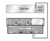
Single Host to Array Connection shows a simple host to array connection. In this configuration, the host connection can be to any port, either SAS fabric.
Figure 2-3 Single Host to Array Connection
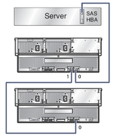
Host to Cascaded Arrays shows a host with two cascaded arrays. In this configuration, the cascaded arrays comsume a total of 108 SAS targets (96 disk targets and 12 expander targets). All of the supported HBAs for the J4500 array can support this number.
Figure 2-4 Host to Cascaded Arrays
Host with Two Direct-Connected Arrays shows a host with two cascaded arrays. In this configuration, the two arrays also comsume a total of 108 SAS targets (96 disk targets and 12 expander targets). All of the supported HBAs for the J4500 array can support this number.
Figure 2-5 Host with Two Direct-Connected Arrays
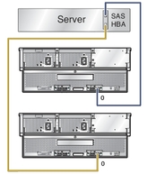
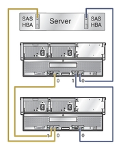
Host with Multipath-Connected Arrays shows an example of multipath cabling using one host, two HBAs and two cascaded arrays. Note that the host links are cascaded in opposite directions from the edge of the SAS fabric so that if one array enclosure fails, there is still host access to the working array enclosure. This configuration supports zoned storage and failover. For more information on configuring multipath, see the Sun Storage J4500 Array System Overview (820-3163).
Figure 2-6 Host with Multipath-Connected Arrays
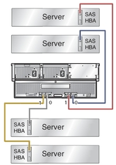
Four Hosts Directly Connected to a Zoned Array shows a color-coded example of four hosts connected in single path configuration to an array. In this configuration, the storage in the array has been separated into four zones. Each host (indicated by a separate cable color) can only see the disks in its assigned zone. In this configuration, each of the hosts must have the Sun Common Array Manager (CAM) proxy agent installed and running, or one of the hosts can act as the CAM management host while the others run the proxy agent. The CAM management host is used to configure and manage zones on the array. For more information on configuring zoning, see the Sun Storage J4500 System Overview (820-3163).
Figure 2-7 Four Hosts Directly Connected to a Zoned Array
