| Skip Navigation Links | |
| Exit Print View | |

|
Sun Storage J4500 Array Service Manual |
1. Introduction to the Sun Storage J4500 Array
1.2 Exterior Features, Controls, and Indicators
1.2.3 Sun Storage J4500 Array Internal Components
2. Configuring and Powering On the Sun Storage J4500 Array
2.1.3 Cabling the SAS Connectors
2.2 Powering On and Off the Array
To Place the Array Into Standby Power Mode
2.2.1 AC Power Failure Auto-Recovery
3. Maintaining the Sun Storage J4500 Array
3.1 Options and Replaceable Components
3.3 Powering Off the Array and Removing It From the Rack
To Remove the Array Enclosure From the Rack
3.4 Removing and Replacing the Hard Disk Drive Access Cover
To Remove the Hard Disk Drive Access Cover
To Replace the Hard Disk Drive Access Cover
To Replace the Front Indicator Board
To Replace the Power Distribution Board
To Replace the System Controller Module
3.7 Upgrading Enclosure Firmware
3.7.1 Ensure Both SAS Fabrics are Upgraded to the Same Firmware Revision Level
4.2 Internal Disk Drive and Fan LEDs
4.3 Diagnostic and Management Tools
4.3.2 Common Array Manager (CAM)
4.4 Troubleshooting Problems with the Array
4.4.2 Check the Event and Performance Logs
4.4.3 Using the Array Management Software to Monitor Enclosure Health
4.4.6 Array Environment Problems
4.5 Resetting the Enclosure Hardware
To Reset the Enclosure Hardware Using the Reset Button
4.6 Clearing the Enclosure Zoning Password
To Clear the Enclosure Zoning Password
B.2 I/O-to-Disk Backplane Connectors
B.2.2 High-Speed Dock Connectors
B.4 Disk Backplane-to-Front Indicator Connector
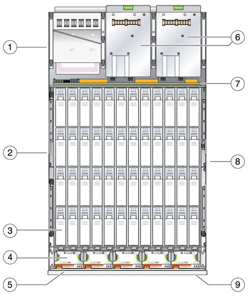
The locations of the replaceable components in the enclosure are shown in Sun Storage J4500 Array Internal Components.
Figure 3-7 Sun Storage J4500 Array Internal Components

Figure Legend
1 System Controller (under power supplies)
2 ESD ground location
3 Hard disk drives (numbered 0-47)
4 Fan tray modules (numbered 0-4)
5 Front indicator board (behind bezel)
6 Power supplies (2)
7 Power Distribution Board (PDB)
8 Hard disk backplane (under chassis plate)
9 Front bezel