| Skip Navigation Links | |
| Exit Print View | |

|
SPARC M5-32 and M6-32 Servers HTML Collection |
Understanding the Hardware Architecture
Understanding the Firmware and Software Environment
General Installation Site Guidelines
Reviewing the Physical Specifications
Leveling Feet and Caster Dimensions
Raised Floor Weight Considerations
Mounting Holes and Cable Routing Floor Cutout Specifications
Reviewing the Power Requirements
Power Cord-to-Power Supply Relationship
Circuit Breaker Capacity Requirements
Heat Dissipation and Airflow Requirements
Cooling Airflow From Ceiling Vents
Cooling Airflow From Perforated Floor Tiles
Measure the Ambient Temperature and Humidity
Preparing the Unloading Route and Unpacking Area
Loading Dock and Receiving Area Requirements
Mandatory Cable Connections and Network Addresses
PDomain Cables and Network Addresses
Oracle VM Server for SPARC Network Addresses
Equipment Needed for Installation
Attach an Antistatic Wrist Strap
Optional Component Installation
Connecting the Front SP Cables
Connecting the Rear Power Cords and Data Cables
Prepare the Cable Routing Brackets
Connect the EMS Network Cables
Powering On the Server for the First Time
Connect Terminals or Emulators to the SP SER MGT Ports
Switch On the Facility Circuit Breakers
Set Oracle ILOM Network Addresses
Set the Altitude of the Server
Oracle Solaris OS Configuration Parameters
Additional Software Configuration and Testing
Understanding the System Architecture
Understanding PCIe Device Root Complexes
Understanding EMS SAS Paths to the Internal Drives
Understanding Internal Drive Device Paths
Understanding Network Port Device Paths
Understanding Configuration Guidelines
Understanding System Administration Resources
Understanding Platform-Specific Oracle ILOM Features
Oracle VM Server for SPARC Overview
Multipathing Software Overview
Oracle ILOM Remote System Console Plus Overview
Oracle Hardware Management Pack Overview
Oracle Enterprise Manager Ops Center
Time Synchronization and NTP Service
Multi-Domain Extensions to ILOM MIBs
Establish a Network Management Connection to Oracle ILOM
Switch Between the Oracle ILOM CLI and the System Console on a Host
Controlling the Server, Domains, and Devices
Resetting the Server, SP, or Domains
Managing the Server's Boot Behavior
Booting and Shutting Down the OS
Configuring Oracle ILOM User Accounts and Roles
Record Network Parameter Values
Viewing the Network Configuration
Administering CMUs, CMPs, and DIMMs
Administering IOUs and PCIe Device Root Complexes
Identifying Domain-Level Commands
Obtain the Server Serial Number
Viewing Server and Component Information
XSCF and Oracle ILOM Command Comparison
Identifying SP Configuration and Administration Commands
Identifying Domain Administration Commands
Identifying Internal Components
Component Service Task Reference
Interpreting Log Files and System Messages
Removing Power From the Server
Servicing Trim Panels and the Kick Plate
Trim Panel Service Preparation
Check a Service Processor Battery
Replace a Service Processor Battery
I/O Switch Board Configuration
Servicing Cable Management Assemblies
Remove a Cable Management Assembly
Install a Cable Management Assembly
Understanding I/O Card Slot Configuration
Understanding I/O Card Slot Device Paths and FRU Paths
Sun Flash Accelerator F40 and F80 PCIe Cards
Locate an I/O Card in the Server
Prepare an I/O Card For Removal
Remove an I/O Card From the Server
Remove an I/O Card From a Carrier
Install an I/O Card in a Carrier
Install an I/O Card in the Server
Remove a Filler Panel From the Server
Remove a Filler Panel From a Carrier
Install a Filler Panel in a Carrier
Install a Filler Panel in the Server
Relocate a Sun Flash Accelerator F40 PCIe Card
Understanding EMS Configurations
Determine Hard Drive Cage and EMS Part Numbers
Servicing HDDs, SSDs, and Drive Filler Panels
Understanding HDD and SSD Slot Configurations
CMU Upgrades in a SPARC M5-32 Server
Display General CMU Information
Display the CMU Quantity and Type
Unpacking and Inspecting a CMU
Servicing the Front Filler Panel
Install the Front Filler Panel
Servicing a Cabled Lower Bus Bar Assembly
Remove a Cabled Lower Bus Bar Assembly
Install a Cabled Lower Bus Bar Assembly
Servicing the Scalability Card Cage
Remove the Scalability Card Cage
Install the Scalability Card Cage
Servicing the Scalability Fans Cable
Remove the Scalability Fans Cable
Install the Scalability Fans Cable
Servicing the Power System Cage
Prepare to Replace Crown Clips on a Bus Bar
Return the Server to Operation
Servicing an I/O Power Cable Assembly
Remove an I/O Power Cable Assembly
Install an I/O Power Cable Assembly
Servicing the Scalability Assembly
Remove the Scalability Assembly
Install the Scalability Assembly
Servicing the Power System Cage to Scalability Assembly Cable
Remove the Power System Cage to Scalability Assembly Cable
Install the Power System Cage to Scalability Assembly Cable
Servicing the PSDB to Scalability Midplane Cable
Remove the PSDB to Scalability Midplane Cable
Install the PSDB to Scalability Midplane Cable
Servicing the Internal Link to Front LED Panel Cable
Remove the Internal Link Cable for the Front LED Panel
Install the Internal Link Cable for the Front LED Panel
Servicing the Rear LED Panel Cable
Remove the Rear LED Panel Cable
Install the Rear LED Panel Cable
Servicing Midplane Power Cables
Prepare to Remove a Midplane Power Cable
Install a Midplane Power Cable
Servicing the I/O Data Cable Assembly
Remove an I/O Data Cable Assembly
Install an I/O Data Cable Assembly
Prepare to Remove the Midplane
Prepare the Old Midplane for Return
Returning the Server to Operation
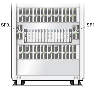
The server contains two dual-redundant SPs (SP0 and SP1) on the front of the server. One of the SPs functions as the Active SP to manage the server, and the other one acts as a Standby SP that will assume the Active SP role in the event of an SP failure.
Note - Either SP (SP0 or SP1) can take the Active SP role. Do not assume that SP0 will take the Active SP role and that SP1 will take the Standby SP role.

Each SP contains two ports:
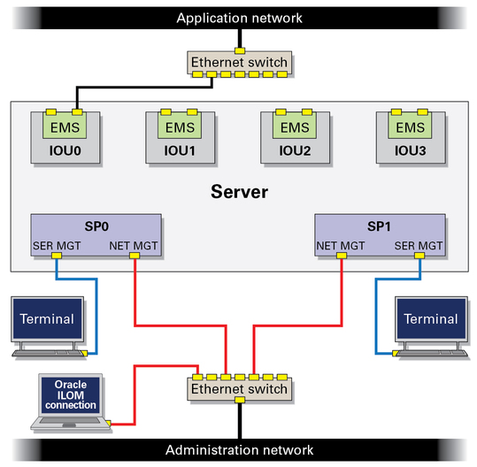
SER MGT port – Connect a Category 5 or better serial cable from this port to a terminal device. During the initial server power on, use this serial connection to monitor the boot process and perform the initial Oracle ILOM configuration.
NET MGT port – Connect a Category 6 or better cable to this 1-GbE port. After the initial server configuration, use this Ethernet connection to monitor and administer the server through the Oracle ILOM console.
In addition to the two SPs, the server contains up to four SPPs. Each SPP manages one DCU in the server. The Active SP and the SPPs communicate with each other over an internal VLAN. For each PDomain, one SPP takes the role of the PDomain-SPP, which manages tasks for the PDomain and provides rKVMS service for that PDomain.
To isolate the Oracle ILOM administration network, you can connect the SP NET MGT cables to a network separate from networks used for server applications. By connecting the NET MGT ports to an Ethernet switch, you can make an Oracle ILOM network connection to either SP.

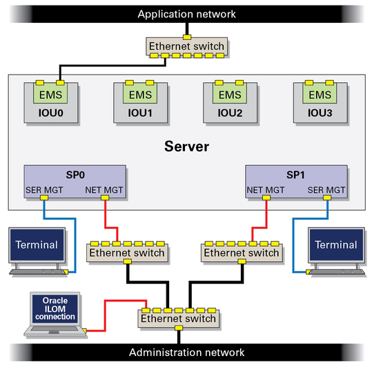
To add redundancy, connect each SP to a different Ethernet switch. Connect these two switches to a third switch, and connect that third switch to the Oracle ILOM console.
