Configuring and Using IPMP in the Service Domain
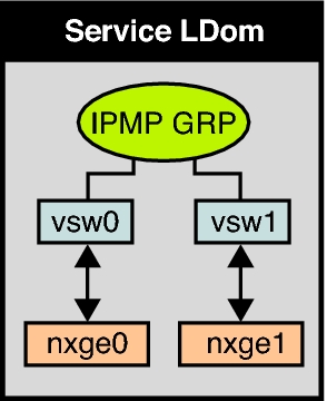
You can configure IPMP in the service domain by configuring virtual switch interfaces into a group. The following diagram shows two virtual switch instances (vsw0 and vsw1) that are bound to two different physical devices. The two virtual switch interfaces can then be created and configured into an IPMP group. In the event of a physical link failure, the virtual switch device that is bound to that physical device detects the link failure. Then, the virtual switch device sends notification of this link event to the IP layer in the service domain, which results in a failover to the other virtual switch device in the IPMP group. The two physical interfaces are nxge0 and nxge1 in Oracle Solaris 10 and net0 and net1 in Oracle Solaris 11. The diagram shows the Oracle Solaris 10 physical interface names.
Figure 11-9 Two Virtual Switch Interfaces Configured as Part of an IPMP Group

Note - The diagram shows the configuration on an Oracle Solaris 10 system. For an Oracle Solaris 11 system, only the interface names change to use the generic names, such as net0 and net1 for nxge0 and nxge1, respectively.