Go to main content

Oracle® ZFS Storage Appliance Installation Guide

Exit Print View

Updated: January 2019


Overview of ZS7-2 Controller

This section provides an overview of the Oracle ZFS Storage ZS7-2 controller. For installation instructions, refer to Installing a ZS7-2 Controller. For service instructions, refer to Servicing the ZS7-2 Controller in Oracle ZFS Storage Appliance Customer Service Manual.

Refer to http://oracle.com/zfsstorage for the most recent component specification.

ZS7-2 Physical Specifications

The ZS7-2 controller chassis dimensions are as follows:

Dimension
Measurement
Dimension
Measurement
Height
3.42 in./8.69 cm
Depth
29.9 in./75.9 cm
Width
17.5 in./44.5 cm
Weight (Maximum)
63 lb./28.6 kg

ZS7-2 Electrical Specifications

The ZS7-2 controller has two hot-swappable rear accessible power supplies with N+N redundancy. To understand the overall power consumption, see Oracle's online power calculator at http://www.oracle.com/goto/powercalculators.

Parameter
AC Power Supplies
Nominal input frequencies
50/60 Hz
Operating input voltage range
100-240 VAC
Rated input current
10 A @ 100 to 127 VAC and 7 A @ 200 to 240 VAC
Maximum power consumption of controller
Refer to the Power Calculator (https://www.oracle.com/goto/powercalculators) and see Oracle Server X7-2L for Watt calculations
Maximum heat output of controller
Refer to the Power Calculator (https://www.oracle.com/goto/powercalculators) and see Oracle Server X7-2L for BTU/hr calculations

ZS7-2 Acoustic Noise Emissions

The workplace-dependent noise level of this product is 8.1 Bels A-weighted Operating, and 5.8 Bels A-weighted Idling (measured Sound Power).

ZS7-2 Configuration Options

The ZS7-2 high-end model incorporates one or two controllers and one to forty-eight disk shelves. Each controller has 11 PCle Gen3 slots in the rear, and 12 3.5" disk slots in the front, two of which are occupied by system disks. Read cache devices are installed in disk shelves; therefore, the remaining ten front disk slots have permanent filler panels. The following table describes the configuration options.

CPU
Memory
System Disks
PCIe Slots
HBA
2x24-core, 2.1 GHz
1.5 TB
2x3.5'' SAS-3
Six dedicated; five available
4-port (4x4) SAS-3 12 Gb/s external

The ZS7-2 mid-range model incorporates one or two controllers and one to sixteen disk shelves. Each controller has 11 PCle Gen3 slots in the rear, and 12 3.5" disk slots in the front, two of which are occupied by system disks. Read cache devices are installed in disk shelves; therefore, the remaining ten front disk slots have permanent filler panels. The following table describes the configuration options.

CPU
Memory
System Disks
PCIe Slots
HBA
2x18-core, 2.3 GHz
512 GB or 1024 GB
2x3.5'' SAS-3
Four dedicated; five available; two unavailable (permanent filler panels)
4-port (4x4) SAS-3 12 Gb/s external

The most recent component specification is located at https://www.oracle.com/storage/nas/index.html.

ZS7-2 Front Panel Components

The ZS7-2 controller drive slots and front panel components are shown in the following figure.

Figure 22  ZS7-2 Front Panel
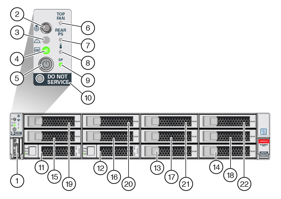
image:The image shows the ZS7-2 front panel components.

1 RFID tag
2 System status LED: Locator (white)
3 System status LED: Service Action Required (amber)
4 System status LED: Power/OK (green)
5 Power button
6 Fan service action required (amber)
7 Power Supply (PS) service action required (amber)
8 Over-temperature warning (amber)
9 Service Processor (SP) OK (green)
10 Do Not Service indicator
11 System disk 0
12 System disk 1
13 Filler panel
14 Filler panel
15 Filler panel
16 Filler panel
17 Filler panel
18 Filler panel
19 Filler panel
20 Filler panel
21 Filler panel
22 Filler panel

ZS7-2 Rear Panel Components

The ZS7-2 controller PCIe slots and rear panel components are shown in the following figure.

Figure 23  ZS7-2 Rear Panel
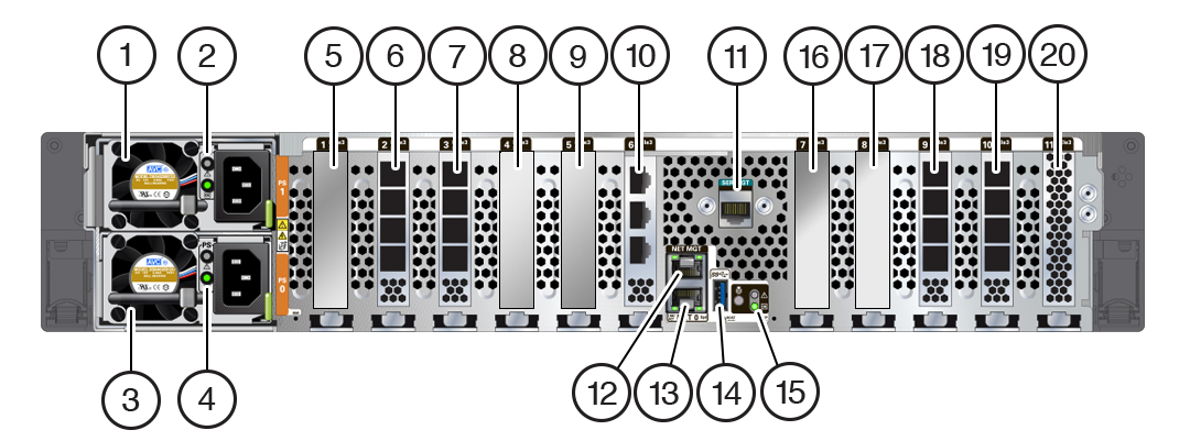
image:The image shows the ZS7-2 high-end model rear panel                             components.

1 Power Supply Unit (PSU) 1
2 PSU 1 status indicators (top to bottom):
  • Attention (amber)

  • Power/OK (green)

3 PSU 0
4 PSU 0 status indicators (top to bottom):
  • Attention (amber)

  • Power/OK (green)

5 Fifth PCIe option (slot 1)
6 External SAS-3 HBA (slot 2)
7 Slot 3:
  • High-end model: External SAS-3 HBA

  • Mid-range model: Filler panel

8 First PCIe option (slot 4)
9 Third PCIe option (slot 5)
10 Cluster interface card (slot 6)
11 Serial management (SER MGT) RJ-45 serial port
12 Service Processor (SP) NET MGT port
13 Network (NET) 100/1000BASE-T RJ-45 Gigabit Ethernet (GbE) port: NET 0
14 USB 3.0 port
15 System status LEDs:
  • Locate (white) - left

  • Attention (amber) - right, top

  • Power/OK (green) - right, bottom

16 Fourth PCIe option (slot 7)
17 Second PCIe option (slot 8)
18 Slot 9:
  • High-end model: External SAS-3 HBA

  • Mid-range model: Filler panel

19 External SAS-3 HBA (slot 10)
20 Internal SAS-3 HBA (slot 11)

For information about how to connect cables to form a cluster, see Connecting Cluster Cables in Oracle ZFS Storage Appliance Cabling Guide.