Connecting Cluster Cables
The cluster interface card provides three redundant links that enable two controllers to communicate with each other. The cluster I/O ports consist of two serial links (0,1) and an Ethernet link. Cluster cabling must be done before powering on either controller, and all three links must be established before configuration can proceed.
Before You Begin
Gather the three Ethernet cables that were supplied for connecting clustered controllers. The ZS7-2 and ZS5-x cluster cables are 2.5-meters in length. Cluster cables or other controllers are 1-meter in length. If supplying your own Ethernet cables, ensure they are straight-through, Category 5 or better, and the correct length.
-
Connect the cluster serial ports of each controller to form a crossover
pattern:
- Connect one Ethernet cable between serial port 0 of one controller and serial port 1 of the other controller.
-
Connect another Ethernet cable between serial port 1 of one controller and
serial port 0 of the other controller.
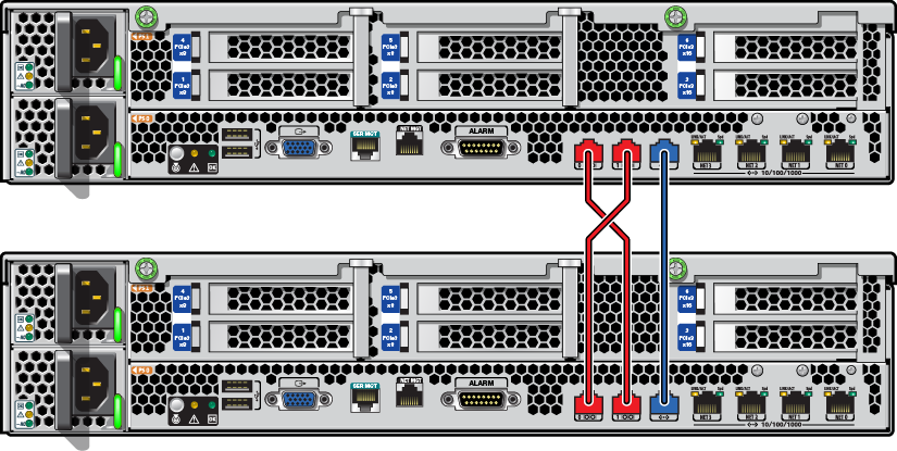
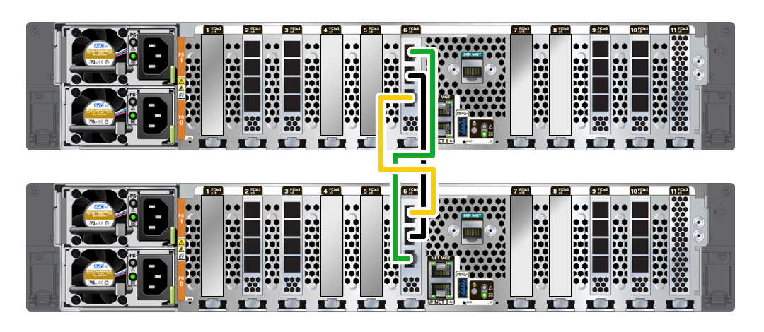
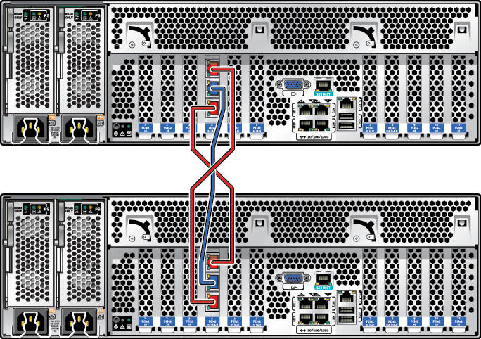
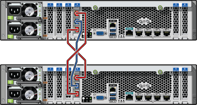
The cables between the serial ports form a crossover pattern, as shown in the following illustrations. For ZS7-2 controllers, use the supplied yellow and green Ethernet cables. Use one cable for step 1a and the other for step 1b; it does not matter which cable you use.
-
Connect one Ethernet cable between the Ethernet ports of each controller.
The following figure shows cluster cabling between two ZS7-2 controllers (high-end model shown). Use the supplied black Ethernet cable.
ZS7-2 Cluster Cabling
The following figure shows cluster cabling between two ZS5-4 controllers.
ZS5-4 Cluster Cabling
The following figure shows cluster cabling between two ZS5-2 controllers.
ZS5-2 Cluster Cabling
The following figure shows cluster cabling between two ZS4-4 controllers.
ZS4-4, ZS3-4, 7420 Cluster Cabling
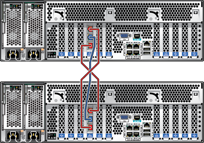
Note - The cluster card for ZS3-4 and 7420 is installed in the Cluster slot, as described in the hardware overview for each controller in Oracle ZFS Storage Appliance Customer Service Manual.The following figure shows cluster cabling between two ZS3-2 controllers.
ZS3-2 Cluster Cabling
