Remove the Front LED Indicator Module
-
Prepare the server for service.
- Power off the server and disconnect the power cords from the power supplies.
- Extend the server into the maintenance position.
- Attach an antistatic wrist strap to your wrist, and then to a metal area on the chassis.
- Remove the server top cover.
-
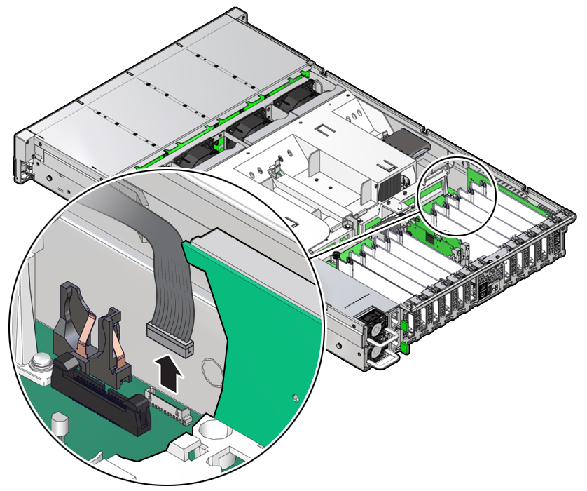
Disconnect the LED indicator module cable from the motherboard.
Note - On the HC server, you might need to disconnect the SAS cable connections from the Oracle Storage 12 Gb SAS PCIe RAID HBA, Internal card in PCIe slot 11 to access the LED indicator module motherboard cable connection. To ease removal of the LED indicator module cable, slightly lift the SAS cable bundles from the cable trough along the left side of the chassis. See Servicing SAS Cables.
-
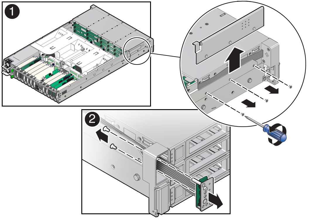
Remove the three No. 2 Phillips screws that secure the FIM cable and Temp
Sensor Access cover to the chassis [1].

-
Lift up and remove the FIM cable and Temp Sensor Access cover from the FIM
cable and Temp Sensor Access cover slot [1].
Set aside the FIM cable and Temp Sensor Access cover.
-
Remove the front LED indicator module [2].
- Remove the two No. 2 Phillips screws that secure the LED indicator module to the server front panel.
-
Remove the LED indicator module and cable from the server front
panel.
Remove the LED indicator module cable by carefully pulling the cable through the cable trough along the left side of the chassis.