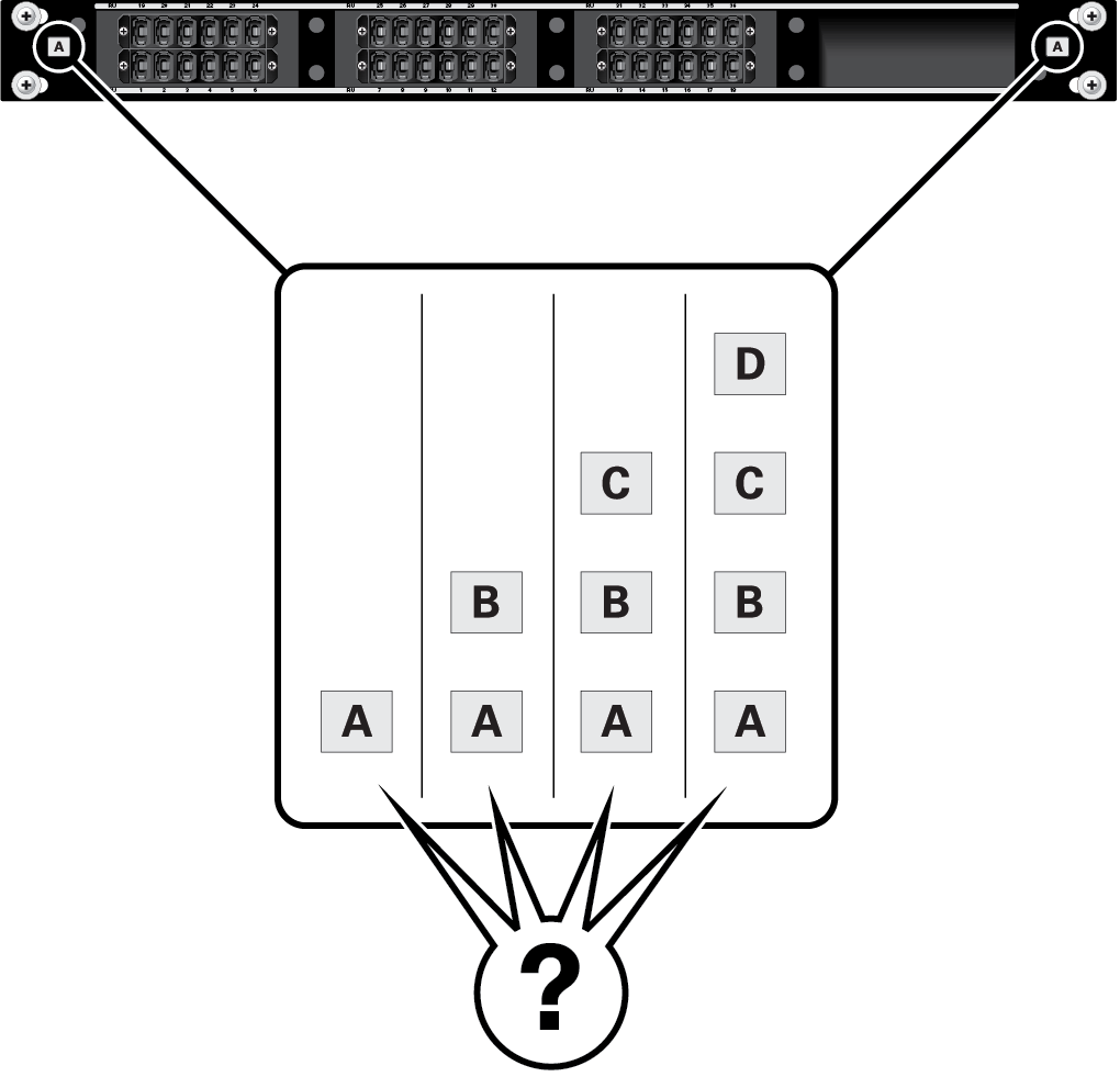
MPO Coupler Panel
The modular system can be ordered with MPO coupler panels preinstalled in lieu of internal Ethernet fiber switches. See Identifying Components. Up to four MPO coupler panels can be installed, based on node configurations and connectivity per node. Within each MPO coupler panel are three fiber coupler modules. Systems are populated with MPO coupler panels starting from slot 37 and going up to slot 40.
-
Panel letter designations A, B, C, or D correspond to the PMT-x interfaces on the node blind-mate interface (VFI connector) at the FBS. (Depending on how many coupler panels are installed, shown as a variable with question marks in the illustration.)
-
Each node supports up to 4 PMT connections (each one a 12-fiber optic interface).
-
Each panel (A, B, C or D) connects to the corresponding PMT-x connection on a node. For example, 30 of the ports on panel A connect to 30 FBS interfaces at PMT-A, respectively.
-
The panel port number connects to the FBS at the corresponding RU slot.
-
Each panel is technology-independent, and the type of data available at each panel's port is dependent upon the node configuration.
