JavaScript is required to for searching.
Skip Navigation Links
Exit Print View
Sun Storage F5100 Flash Array Topic Set
search filter icon
search icon

Document Information

Preface

Related Documentation

Documentation, Support, and Training

Documentation Feedback

Installation

Installing the System

Preparing for Installation

Rackmounting the System

Cabling the System

Power On

Managing the System

Power Off

Service

Sun Storage F5100 Flash Array Overview

Overview

Replaceable Components

Hot-Swappable Components

Obtaining the Chassis Serial Number

Diagnosing System Faults

Choosing a Method for Diagnosing Faults

Diagnosing Faults With Sun StorageTek Common Array Manager Software

Diagnosing Faults With LEDs and Indicators

Troubleshooting Components

Preparing to Service the System

Safety Information

Service Preparation Reference

Powering the System Off

Performing an Antistatic Discharge

Positioning the Chassis

Accessing Internal Components

Replacing System Components

Component Overview

Customer-Replaceable and Field-Replaceable Components

Replacing Flash Modules

Remove a Flash Module

Install a Flash Module

Verify Flash Module Replacement

Replacing a Fan Module

Remove a Fan Module

Install a Fan Module

Verify Fan Module Replacement

Replacing a Power Supply

Remove a Power Supply

Install a Power Supply

Verify Power Supply Replacement

Replacing an Energy Storage Module

Remove an Energy Storage Module

Install an Energy Storage Module

Verify Energy Storage Module Replacement

Replacing Fan Boards

Remove a Fan Board

Install a Fan Board

Verify Fan Board Replacement

Replacing the Motherboard Assembly

Remove the Motherboard Assembly

Install the Motherboard Assembly

Verify Motherboard Replacement

Replacing a Power Distribution Board

Remove a Power Distribution Board

Install a Power Distribution Board

Verify Power Distribution Board Replacement

Replacing the Connector Board Assembly

Remove the Connector Board Assembly

Install a Connector Board Assembly

Verify Connector Board Replacement

Replacing the Energy Storage Backplane

Remove the Energy Storage Backplane

Install the Energy Storage Backplane

Verify Energy Storage Backplane Replacement

Returning the System to Service

Replace the Top Chassis Cover

Install the Chassis to Maintenance Position

Return the System to the Fully Installed Position

Install AC Power Cord Retention Clips

Power On the System

Index

Install a Connector Board Assembly

  1. Insert the cable that connects the board to the PDB, lower the new connector board into the chassis at a slight angle, and tilt it back toward the side of the chassis until it is vertical as shown in panels 1 and 2 of Installing the Connector Board Assembly.

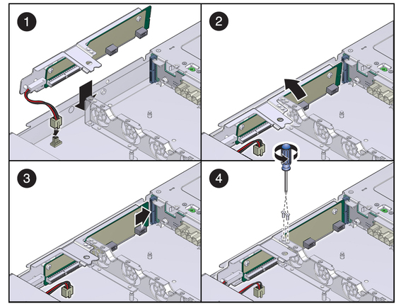
    The connector board fits over a series of standoffs in the chassis side wall.

  2. Slide the connector board forward toward the energy storage backplane until it plugs into the backplane as shown in panel 3 of Installing the Connector Board Assembly.
  3. Using a No. 1 Phillips screwdriver, replace and tighten the two screws that secure the connector board to the energy storage backplane as shown in panel 2 of Installing the Connector Board Assembly.

    Figure 41 Installing the Connector Board Assembly

  4. Reinstall the power distribution board.

    Refer to Install a Power Distribution Board.

  5. Reinstall the motherboard assembly.

    Refer to Install the Motherboard Assembly.

  6. Reinstall both fan boards.

    Refer to Install a Fan Board.

  7. Reinstall the fan modules.

    Refer to Install a Fan Module.

  8. Replace the top chassis cover.

    Refer to Replace the Top Chassis Cover.

  9. Return the system to the installed position.

    Refer to Return the System to the Fully Installed Position.

  10. Reconnect any power cables that were disconnected before the connector board was removed.
  11. Restore power to the system.

    Refer to Power On the System.