| Skip Navigation Links | |
| Exit Print View | |

|
Sun Storage F5100 Flash Array Topic Set |
Documentation, Support, and Training
Sun Storage F5100 Flash Array Overview
Obtaining the Chassis Serial Number
Choosing a Method for Diagnosing Faults
Diagnosing Faults With Sun StorageTek Common Array Manager Software
Diagnosing Faults With LEDs and Indicators
Preparing to Service the System
Performing an Antistatic Discharge
Customer-Replaceable and Field-Replaceable Components
Verify Flash Module Replacement
Verify Power Supply Replacement
Replacing an Energy Storage Module
Remove an Energy Storage Module
Install an Energy Storage Module
Verify Energy Storage Module Replacement
Replacing the Motherboard Assembly
Remove the Motherboard Assembly
Install the Motherboard Assembly
Verify Motherboard Replacement
Replacing a Power Distribution Board
Remove a Power Distribution Board
Install a Power Distribution Board
Verify Power Distribution Board Replacement
Replacing the Connector Board Assembly
Remove the Connector Board Assembly
Install a Connector Board Assembly
Verify Connector Board Replacement
Replacing the Energy Storage Backplane
Remove the Energy Storage Backplane
Install the Energy Storage Backplane
Verify Energy Storage Backplane Replacement
Returning the System to Service
Install the Chassis to Maintenance Position
Return the System to the Fully Installed Position
Note - The system must be placed in active-standby power mode before this component is replaced. This component is customer replaceable.
If you plan to remove the AC power cords from the system, before you do so, note which FMod the Common Array Manager (CAM) software identified as faulted so you can locate it during replacement. Once AC power has been removed from the system, the LED on the faulty FMod will not be illuminated.
Refer to Perform Static Discharge Procedures.
Refer to Access Internal Components.
If an amber LED is on, the component is faulty and should be replaced.
Note - If AC power is removed from the system, the LEDs will not illuminate. In this case, refer to the Common Array Manager (CAM) software messaging to determine which FMod faulted.
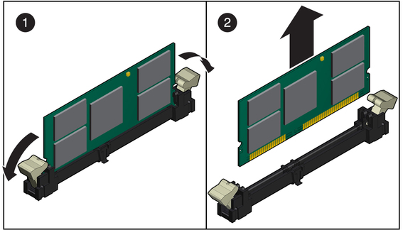
Undo the latches on each end of the FMod and remove it as shown Removing an FMod.
Figure 22 Removing an FMod
