| Skip Navigation Links | |
| Exit Print View | |

|
Sun Storage F5100 Flash Array Topic Set |


Documentation, Support, and Training
Sun Storage F5100 Flash Array Overview
Obtaining the Chassis Serial Number
Choosing a Method for Diagnosing Faults
Diagnosing Faults With Sun StorageTek Common Array Manager Software
Diagnosing Faults With LEDs and Indicators
Preparing to Service the System
Performing an Antistatic Discharge
Customer-Replaceable and Field-Replaceable Components
Verify Flash Module Replacement
Verify Power Supply Replacement
Replacing an Energy Storage Module
Remove an Energy Storage Module
Install an Energy Storage Module
Verify Energy Storage Module Replacement
Replacing the Motherboard Assembly
Remove the Motherboard Assembly
Install the Motherboard Assembly
Verify Motherboard Replacement
Replacing a Power Distribution Board
Install a Power Distribution Board
Verify Power Distribution Board Replacement
Replacing the Connector Board Assembly
Remove the Connector Board Assembly
Install a Connector Board Assembly
Verify Connector Board Replacement
Replacing the Energy Storage Backplane
Remove the Energy Storage Backplane
Install the Energy Storage Backplane
Verify Energy Storage Backplane Replacement
Returning the System to Service
Install the Chassis to Maintenance Position
Return the System to the Fully Installed Position
Note - The system must be completely powered down before this component is replaced. This component must be replaced only by qualified service technicians. Contact your Sun Service representative for assistance.
Refer to Completely Power Off the System.
Refer to Perform Static Discharge Procedures.
This task involves removing all cables, moving the rack into maintenance position, and then removing the chassis from the rack. Refer to Remove the Chassis From the Rack.
Refer to Access Internal Components.
Refer to Remove the Motherboard Assembly.
Refer to Remove a Power Supply.
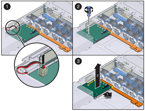
 | Caution - If you are removing the PDB/bus bar assembly to access other components and will return the PDB or bus bar to the system, place them on an antistatic mat when you remove them. |
Figure 38 Removing the PDB From the Chassis


|