Front Panel Features
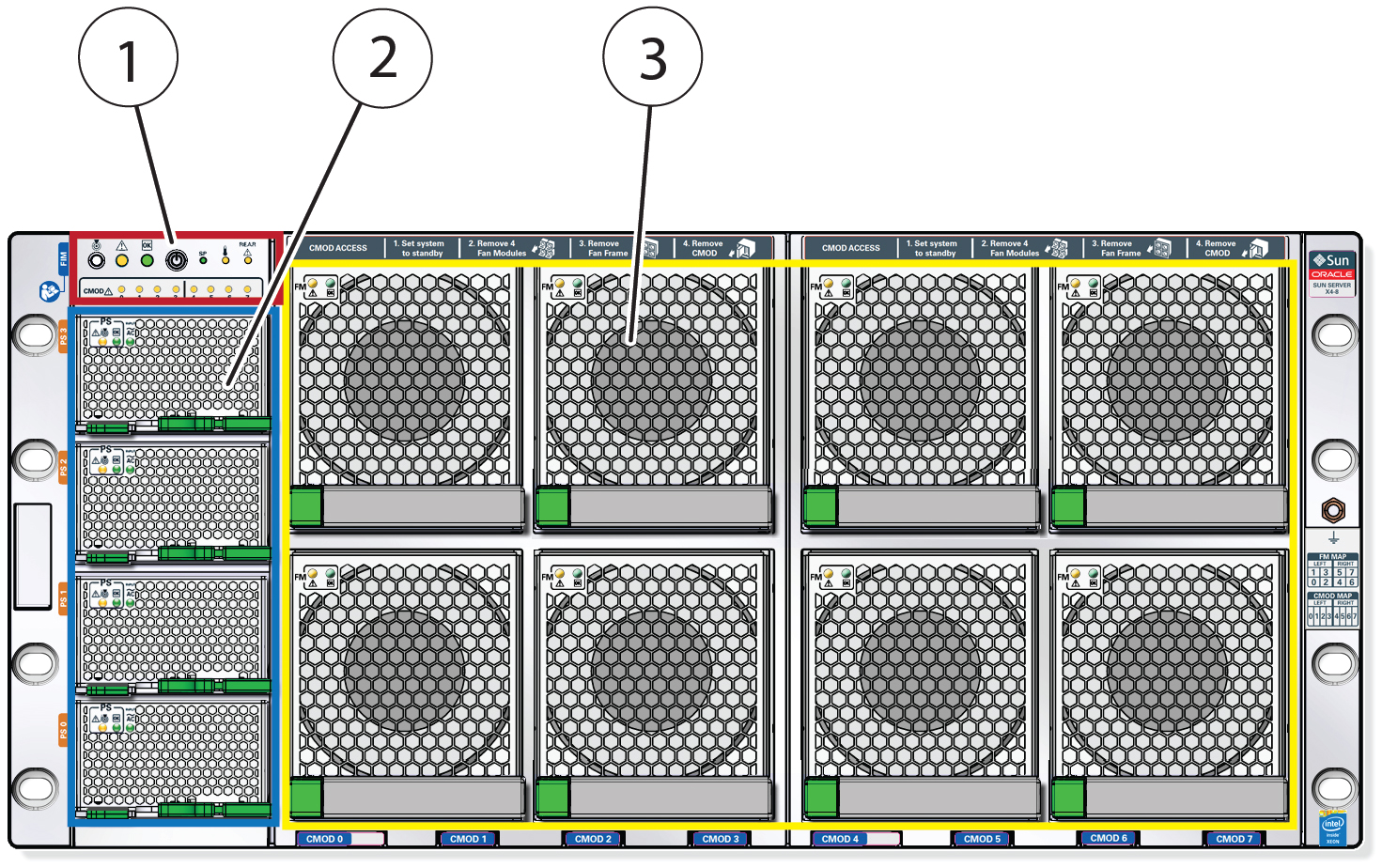
The following figure shows the Sun Server X4-8 front panel and describes its
components:

|
|
|
1
|
Front indicator module
|
|
2
|
Power supplies 0 (bottom) through 3 (top)
|
|
3
|
Fan modules FM 0 through FM 7:
-
Top row: 1, 3, 5, 7
-
Bottom row: 0, 2, 4, 6
|
|
Front Indicator Module
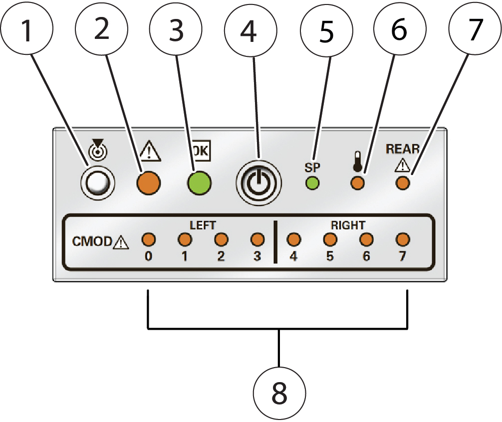
The following figure shows the controls and indicators on the front indicator
module:

|
|
|
1
|
Chassis locator button and indicator
|
|
2
|
Chassis fault indicator
|
|
3
|
Power OK indicator
|
|
4
|
Recessed power button
|
|
5
|
Service processor OK indicator
|
|
6
|
Chassis temperature fault indicator
|
|
7
|
Chassis back fault indicator
|
|
8
|
CMOD fault indicators 0 - 7 (from left to right)
Note -
The server contains either four or eight CMODs (compute
modules), located behind the fans, and designated from left
to right as CMOD 0 through CMOD 7. Each CMOD has a
corresponding indicator.
|
|
Power Supply Controls and Indicators
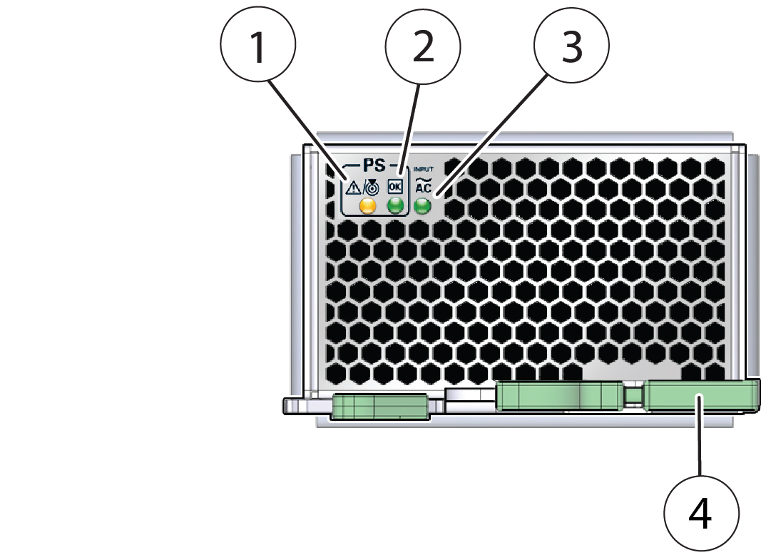
The following figure shows the power supply controls and indicators:

|
|
|
1
|
PSU fault/locate indicator
|
|
2
|
PSU OK indicator (power to host is OK)
|
|
3
|
PSU AC OK indicator (AC input power is OK)
|
|
4
|
Release latch
|
|
Fan Module Controls and Indicators
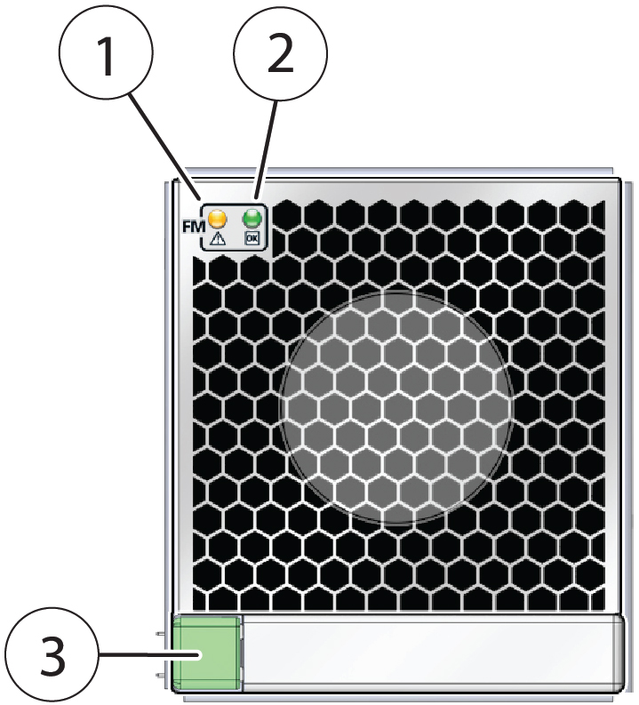
The following figure shows the controls and indicators on the fan module:

|
|
|
1
|
Fault indicator
|
|
2
|
OK indicator
|
|
3
|
Release latch
|
|


