Install the Right LED/USB Indicator Module
-
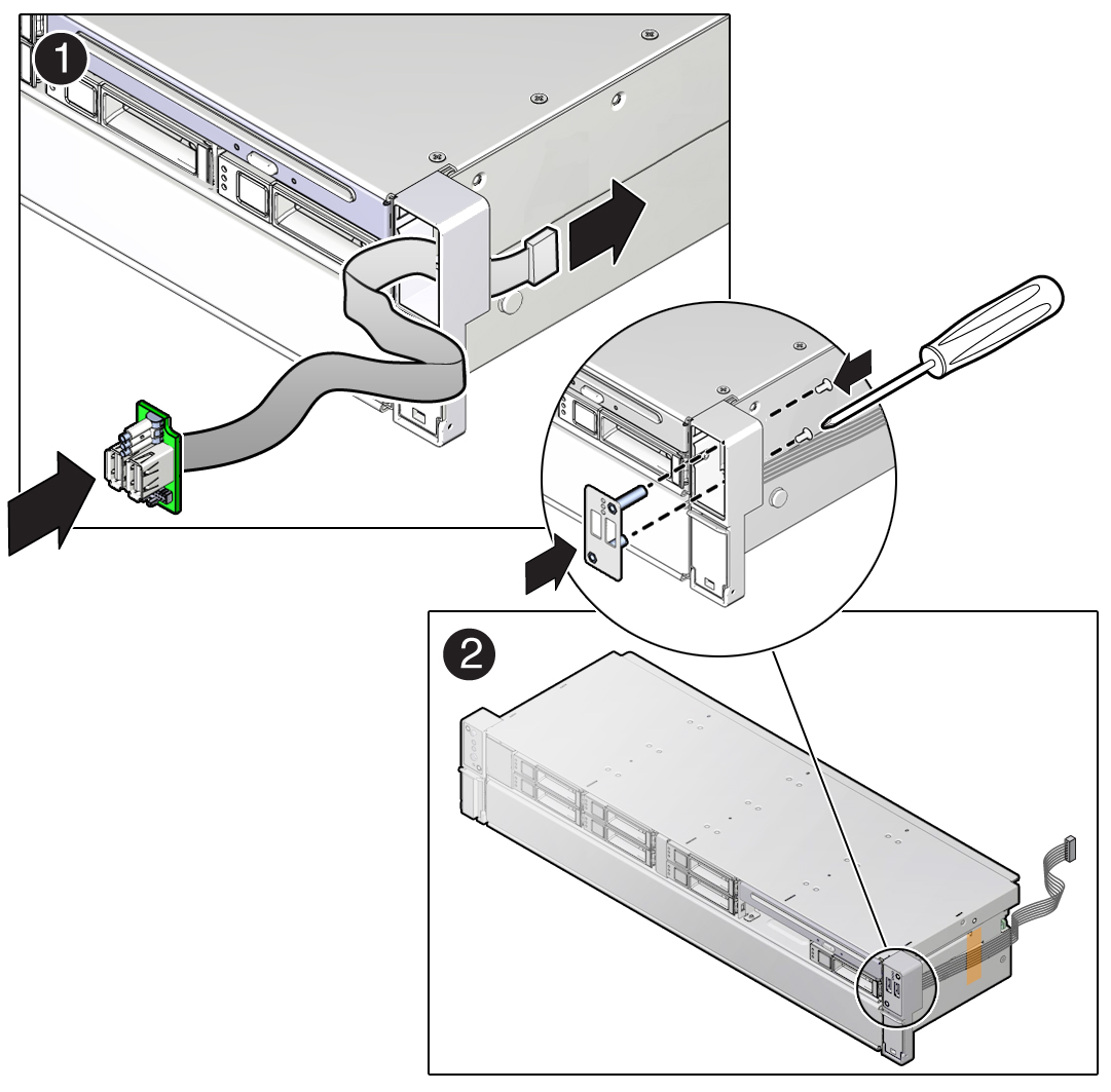
Install the right LED/USB indicator module.
-
Push the LED/USB indicator module and cable through the right LED
housing on the server front panel [1].
If necessary, use a piece of capping tape to secure the cable to the side of the disk cage assembly.

- Insert and tighten the two No. 2 Phillips screws to secure the LED/USB indicator module to the server front panel [2].
-
Push the LED/USB indicator module and cable through the right LED
housing on the server front panel [1].
-
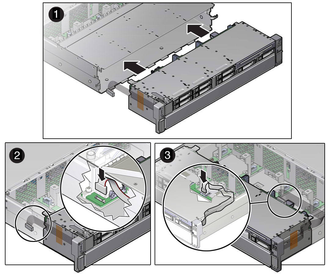
Gently lift the disk cage assembly and set it into the server chassis
[1].
Slightly push the disk cage assembly into the server chassis to ensure that the disk cage screw holes are correctly aligned with the server chassis.

- Reconnect the left LED indicator module cable and the right LED/USB indicator module cable to the motherboard [2 and 3].
-
Reconnect all cables to the front storage drive backplane.
See the procedures for your storage drive configuration in Servicing the Front and Rear Storage Drive Backplanes (FRU).
-
Install the fan modules in the server.
See Install a Fan Module.
-
Depending on your server's storage drive configuration, do one of the
following:
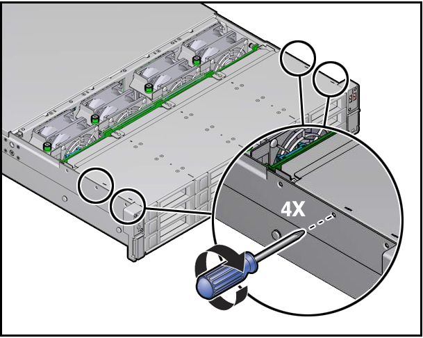
- If your server is configured with twelve 3.5-inch storage drives or twenty-four 2.5-inch storage drives, perform the following procedures.
- If your server is configured with eight 2.5-inch storage drives, install the server disk cage cover.
-
Return the server to operation.
- Install the server top cover.
- Return the server to the normal rack position.
-
Reconnect the power cords to the power supplies, and power on the
server.
See Reconnect Power and Data Cables and Power On the Server. Verify that the power supply AC OK LED is lit.
