Install the Server (4-Post, 19-Inch Sliding Rails With CMA Rack Kit)
 | Caution - You must install the server into a rack following these instructions for the 4-post, 19-inch sliding rails with CMA kit. If you deviate from these instructions when installing the server, your installation will not be supported. |
Server racks can have either square or round mounting holes in the posts. These instructions can be used for both types of racks.
- Gather the required tools.
-
Read the server cautions.
See Handling Precautions and ESD Precautions.
-
Read the rack cautions and stabilize the rack.
See Rack Cautions and Stabilize the Rack.
-
If you are changing the rack kit on an existing server in your data
center, perform these steps:
- Shut down the server, and remove the power and data cables.
- Remove the server from the rack, and place it on an antistatic mat.
- Remove the existing mounting brackets from the server and rack, if applicable.
-
Open the standard hardmount rail kit and the sliding rail kit with the
CMA, and confirm that all of the components are present.
For a description of the kit components, see 19-Inch Sliding Rail Kit With the CMA.
- Remove the hardmount brackets and four M5 x 4.5 mm flathead Phillips screws from the standard hardmount kit.
-
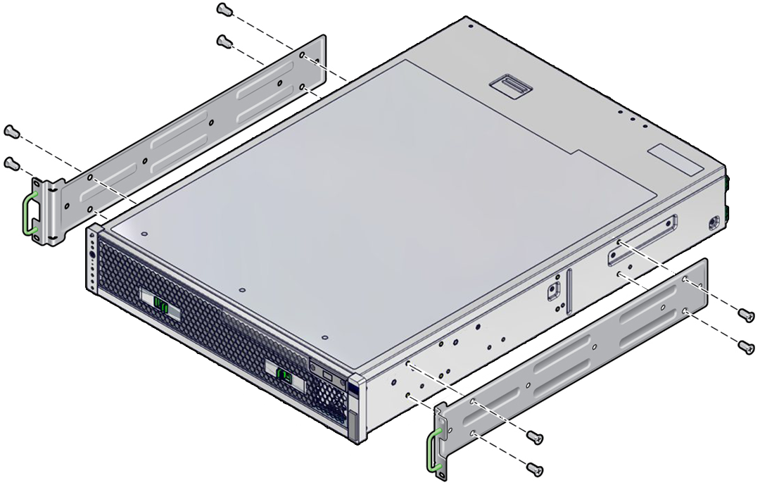
Attach the front, right and left hardmount brackets to the sides of the
server.
Use four M5 x 4.5 mm flathead Phillips screws for each side.
- Disassemble the sliding rails by pressing the release buttons and pulling the rail glides out of the sliding rails.
-
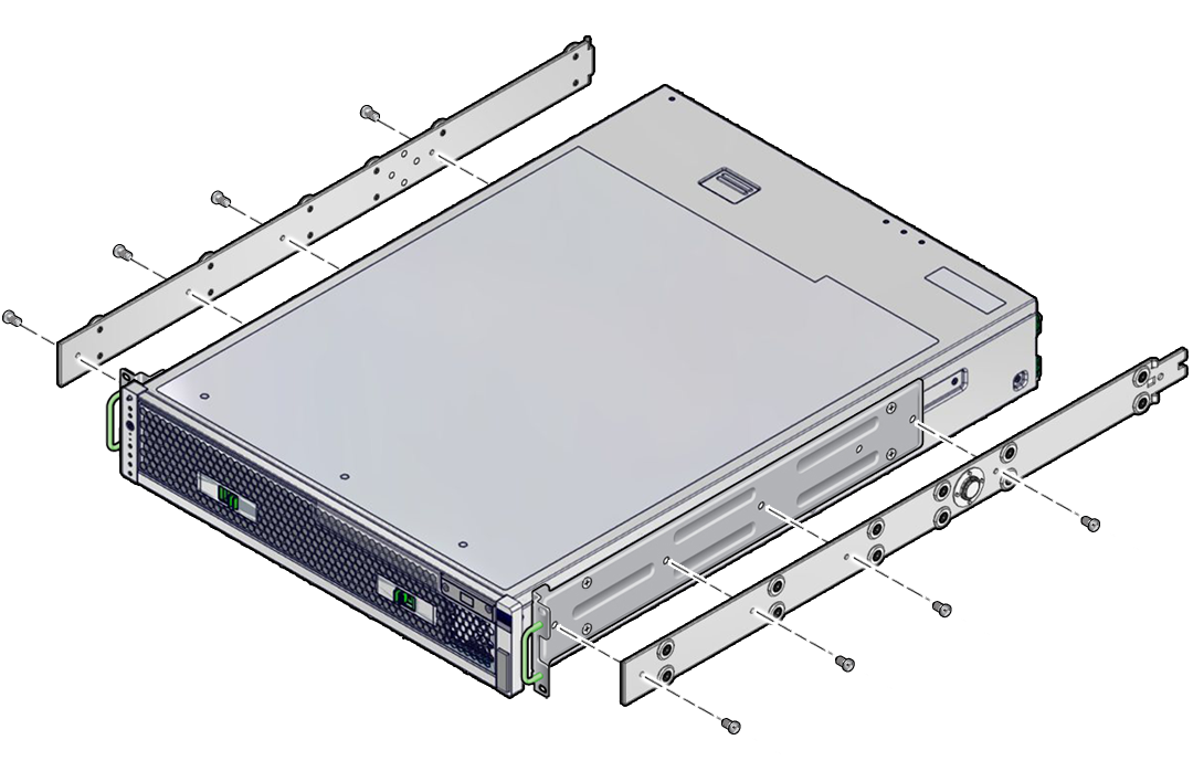
Attach the rail glides to the hardmount brackets.
Use four M4 x 5 mm panhead screws for each rail glide.
-
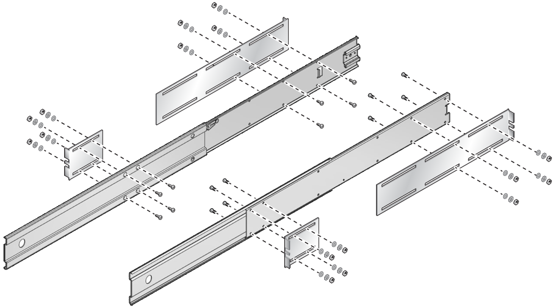
Loosely install the L-brackets to the sliding rails.
Use four M5 x 12 mm panhead screws, four flat washers, four star washers, and four nuts for each L-bracket.
-
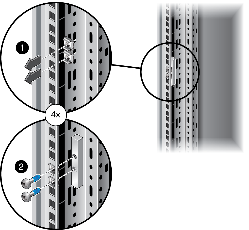
Loosely install the threaded screw plate and cage nuts in the four posts
at the appropriate height.
-
For square-hole racks, use two cage nuts and two M6 shoulder
screws for each threaded screw plate.
-
For round-hole racks, use two U-clips and two M6 shoulder screws
for each threaded screw plate.
The U-clips slip over the post holes, and the mounting brackets are installed in the same manner as the square-hole rack.
-
For square-hole racks, use two cage nuts and two M6 shoulder
screws for each threaded screw plate.
-
Install a cage nut or U-clip in both front posts for securing the server
into the rack.
-
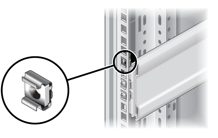
For square-hole racks, use one cage nut per post.
These cage nuts are used to secure the server into the rack. The security screws go through the hardmount brackets and in to the cage nuts.
-
For round-hole racks, install one U-clip per post directly above
and below the thread plate screws.
The U-clips slip over the post holes in the round-hole rack.
-
For square-hole racks, use one cage nut per post.
-
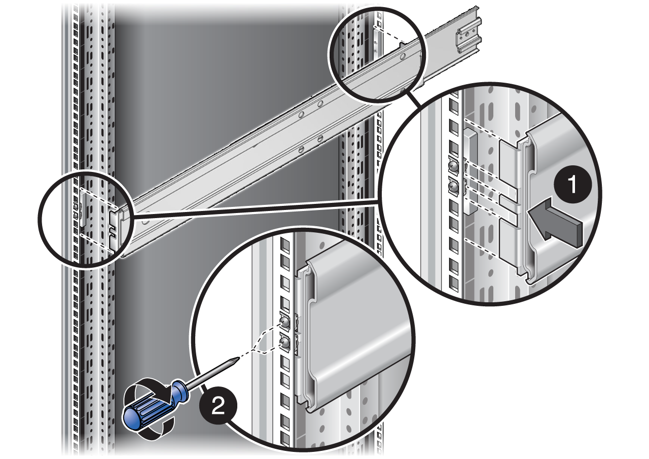
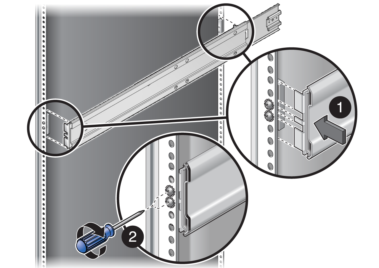
Install the sliding rail, L-bracket assemblies into the threaded screw
plates.
-
For square-hole racks, install the assemblies as shown
here.
-
For round-hole racks, install the assemblies as shown here.
-
For square-hole racks, install the assemblies as shown
here.
- Secure the L-bracket assemblies to the posts.
- Tighten the sliding rail screws.
-
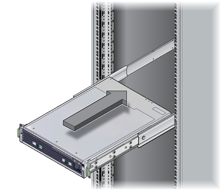
Extend the slide assemblies until they lock open, and slowly install the
server into the slide assemblies.
This illustration shows the square-hole rack. This step is the same for the round-hole rack.
-
Press the release buttons, and slide the server completely into the
rack.
This step is the same for the round-hole rack.
-
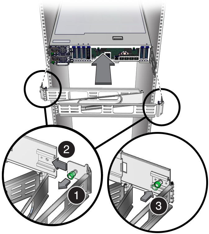
Attach the right and left sides of the CMA to the rear of the slide
assembly (right) and server (left).
This illustration shows the square-hole rack. This step is the same for the round-hole rack.
The green, spring-loaded handles should point inward. Pull the green handles out and release it when the holes are aligned. The left CMA flange fits into key-hole notches on the end of the left glide rail.
-
Extend the server to the service position to ensure that the CMA expands
properly.
This step is the same for the round-hole rack.
-
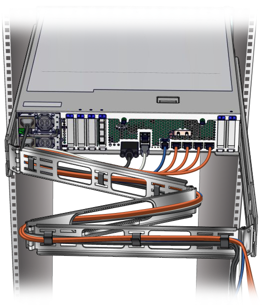
Route and secure the cables in the CMA.
This illustration shows the square-hole rack. This step is the same for the round-hole rack.
-
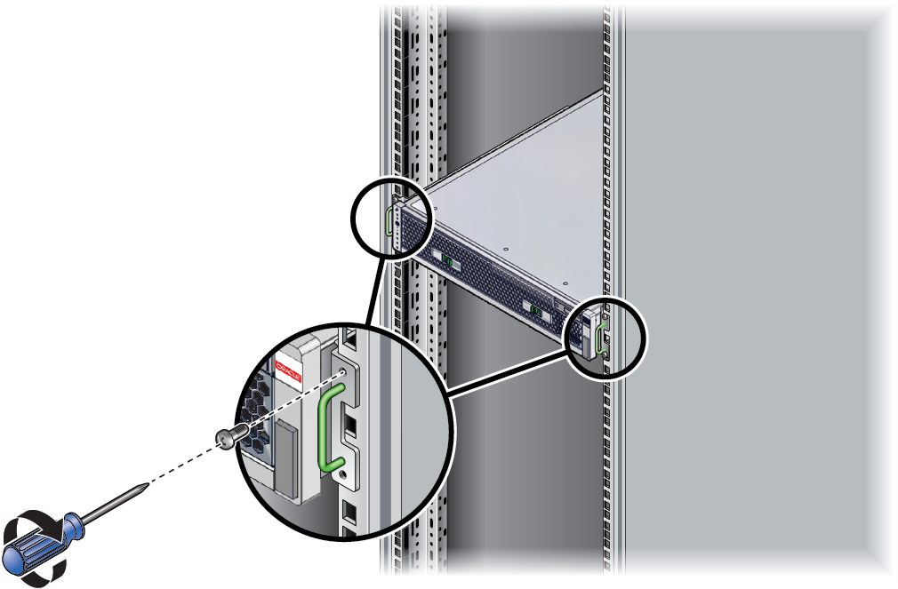
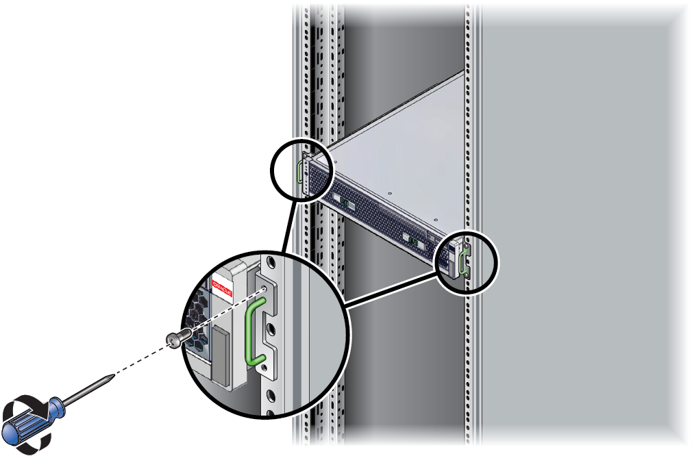
Install the security screws to secure the server into the rack.
-
For square-hole racks, use one M6 x 13 mm shoulder screw for each
post.
-
For round-hole racks, use one M6 x 13 mm shoulder screw for each
post.
-
For square-hole racks, use one M6 x 13 mm shoulder screw for each
post.
-
Consider your next step:
- For existing servers, return the server to operation by following the steps in the service manual.
- For new servers, continue the installation by following the steps in Connecting Cables.