Assemble the DC Input Power Cord
Assemble one DC input power cable for each DC power input to your server.
-
Verify that you have met these conditions:
- Install a DC power source that meets the server's input power specifications.
-
Secure DC power cables that meet the server's power cabling
specifications.
See DC Power Source, Power Connection, and Grounding Requirements.
- Attach the DC input plug to the DC input power cables. The input plug is provided in the server's shipping kit.
-
If the power cables are already connected to a DC power source,
de-energize the cables by removing fuses, opening circuit breakers, or
turning off the DC source.

Caution - Do not proceed with these instructions until you are sure that there is no voltage present on the DC power cables.
-
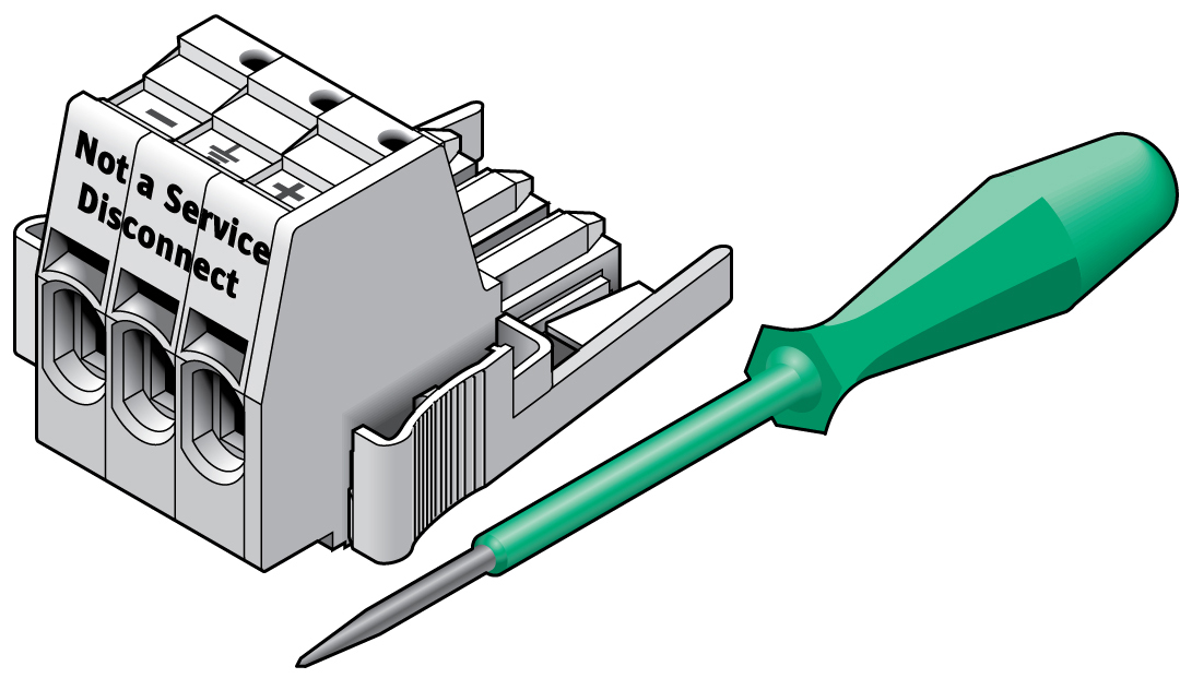
Identify the parts that you will use to assemble the DC input power
cables.
For each cable, you need the items shown in this illustration. These items are included in the shipping kit that came with your server.

-
Locate the three wires coming from your DC power source that will be used
for the connection to your server.
-
-48V or -60V (negative terminal)
-
Chassis ground
-
-48V or -60V Return (positive terminal)
Note - Depending on the DC power source, the -48V or -60V (negative terminal) might be marked with a minus (-) symbol. The -48V or -60V Return (positive terminal) might be marked with a positive (+) symbol.
-
-
Strip 1/2 in. (13 mm) of insulation from each of the wires coming from the
DC power source.
Do not strip more than 1/2 in. (13 mm) from each wire. Doing so leaves uninsulated wire exposed from the DC connector after the assembly is complete.
 No.Description11/2 in. (13 mm) maximum
 -
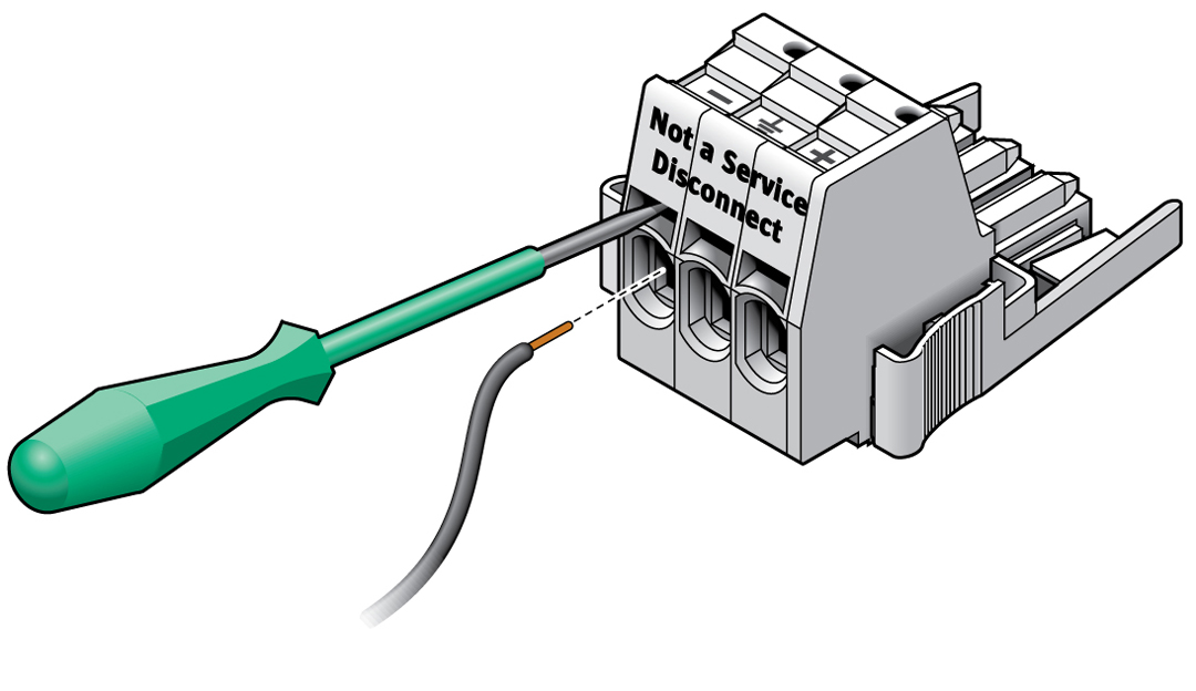
Open the cage clamp for this section of the DC input plug.
Insert the cage clamp tool (or small screwdriver) into the rectangular hole directly above the hole in the DC input plug where you want to insert the first wire. Press down on the cage clamp operating lever.
-
Feed the exposed section of the appropriate wire into the round hole in
the DC input plug.
 No.Description1Top of connector2From -48V or -60V return3From chassis ground (green/yellow)4From -48V or -60V
Note - If you need to remove a wire from the DC input plug, insert the cage clamp operating lever or a small screwdriver and pull the wire from the DC input plug. - Release the lever or remove the tool to secure the wire into the connector.
- Repeat the procedures for the other two wires to complete the assembly of the DC input power cable.
- Repeat this procedure to create as many DC input power cables as you need for your unit.