
The Oracle Private Cloud Appliance consists of an Oracle Rack Cabinet 1242 base, populated with the hardware components identified in Figure 1.1.
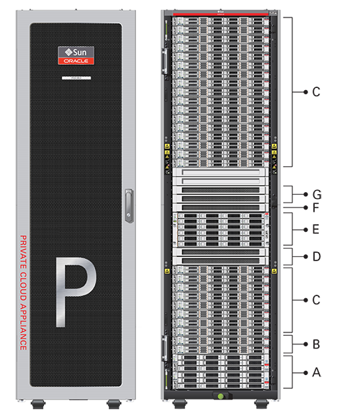
Table 1.1 Figure Legend
Item | Quantity | Description |
|---|---|---|
A | 2 | Oracle ZFS Storage Appliance ZS7-2 controller server |
B | 2 | Oracle Server X8-2, used as management nodes |
C | 2-25 | Oracle Server X8-2, used as virtualization compute nodes (Due to the power requirements of the Oracle Server X8-2, if the appliance is equipped with 22kVA PDUs, the maximum number of compute nodes is 22. With 15KVA PDUs the maximum is 13 compute nodes.) |
D | 2 | Cisco Nexus 9336C-FX2 Switch, used as leaf/data switches |
E | 1 | Oracle ZFS Storage Appliance ZS7-2 disk shelf |
F | 1 | Cisco Nexus 9348GC-FXP Switch |
G | 2 | Cisco Nexus 9336C-FX2 Switch, used as spine switches |
At the heart of each Oracle Private Cloud Appliance installation is a pair of management nodes. They are installed in rack units 5 and 6 and form a cluster in active/standby configuration for high availability: both servers are capable of running the same services and have equal access to the system configuration, but one operates as the master while the other is ready to take over the master functions in case a failure occurs. The master management node runs the full set of services required, while the standby management node runs a subset of services until it is promoted to the master role. The master role is determined at boot through OCFS2 Distributed Lock Management on an iSCSI LUN, which both management nodes share on the ZFS Storage Appliance installed inside the rack. Because rack units are numbered from the bottom up, and the bottom four are occupied by the ZFS Storage Appliance controllers, the master management node is typically the server in rack unit 5. It is the only server that must be powered on by the administrator in the entire process to bring the appliance online.
For details about how high availability is achieved with Oracle PCA, refer to Section 1.5, “High Availability”.
When you power on the Oracle Private Cloud Appliance for the first time, you can change the factory default IP configuration of the management node cluster, so that it can be easily reached from your data center network. The management nodes share a Virtual IP, where the management web interface can be accessed. This virtual IP is assigned to whichever server has the master role at any given time. During system initialization, after the management cluster is set up successfully, the master management node loads a number of Oracle Linux 6 services, in addition to Oracle VM and its associated MySQL database – including network, sshd, ntpd, iscsi initiator, dhcpd – to orchestrate the provisioning of all system components. During provisioning, all networking and storage is configured, and all compute nodes are discovered, installed and added to an Oracle VM server pool. All provisioning configurations are preloaded at the factory and should not be modified by the customer.
For details about the provisioning process, refer to Section 1.4, “Provisioning and Orchestration”.
The compute nodes in the Oracle Private Cloud Appliance constitute the virtualization platform. The compute nodes provide the processing power and memory capacity for the virtual servers they host. The entire provisioning process is orchestrated by the management nodes: compute nodes are installed with Oracle VM Server 3.4.x and additional packages for Software Defined Networking. When provisioning is complete, the Oracle Private Cloud Appliance Controller Software expects all compute nodes in the same rack to be part of the same Oracle VM server pool.
For hardware configuration details of the compute nodes, refer to Server Components in the Oracle Private Cloud Appliance Installation Guide.
The Oracle Private Cloud Appliance Dashboard allows the administrator to monitor the health and status of the compute nodes, as well as all other rack components, and perform certain system operations. The virtual infrastructure is configured and managed with Oracle VM Manager.
The Oracle Private Cloud Appliance offers modular compute capacity that can be increased according to business needs. The minimum configuration of the base rack contains just two compute nodes, but it can be expanded by one node at a time up to 25 compute nodes. Apart from the hardware installation, adding compute nodes requires no intervention by the administrator. New nodes are discovered, powered on, installed and provisioned automatically by the master management node. The additional compute nodes are integrated into the existing configuration and, as a result, the Oracle VM server pool offers increased capacity for more or larger virtual machines.
Because of the diversity of possible virtualization scenarios it is difficult to quantify the compute capacity as a number of virtual machines. For sizing guidelines, refer to the chapter entitled Configuration Maximums in the Oracle Private Cloud Appliance Release Notes.
The Oracle ZFS Storage Appliance ZS7-2, which consists of two controller servers installed at the bottom of the appliance rack and disk shelf about halfway up, fulfills the role of 'system disk' for the entire appliance. It is crucial in providing storage space for the Oracle Private Cloud Appliance software.
A portion of the disk space, 3TB by default, is made available for customer use and is sufficient for an Oracle VM storage repository with several virtual machines, templates and assemblies. The remaining part of approximately 100TB in total disk space can also be configured as a storage repository for virtual machine resources. Further capacity extension with external storage is also possible.
The hardware configuration of the Oracle ZFS Storage Appliance ZS7-2 is as follows:
Two clustered storage heads with two 14TB hard disks each
One fully populated disk chassis with twenty 14TB hard disks
Four cache disks installed in the disk shelf: 2x 200GB SSD and 2x 7.68TB SSD
RAID-1 configuration, for optimum data protection, with a total usable space of approximately 100TB
The storage appliance is connected to the management subnet
(192.168.4.0/24) and the
storage subnet
(192.168.40.0/24). Both heads
form a cluster in active-passive configuration to guarantee
continuation of service in the event that one storage head
should fail. The storage heads share a single IP in the storage
subnet, but both have an individual management IP address for
convenient maintenance access. The RAID-Z2 storage pool contains
two projects, named OVCA and
OVM .
The OVCA project contains all
LUNs and file systems used by the Oracle PCA software:
LUNs
Locks(12GB) – to be used exclusively for cluster locking on the two management nodesManager(200GB) – to be used exclusively as an additional file system on both management nodes
File systems:
MGMT_ROOT– to be used for storage of all files specific to the Oracle Private Cloud ApplianceDatabase– placeholder file system for databasesIncoming(20GB) – to be used for FTP file transfers, primarily for Oracle Private Cloud Appliance component backupsTemplates– placeholder file system for future useUser– placeholder file system for future useYum– to be used for system package updates
The OVM project contains all
LUNs and file systems used by Oracle VM:
LUNs
iscsi_repository1(3TB) – to be used as Oracle VM storage repositoryiscsi_serverpool1(12GB) – to be used as server pool file system for the Oracle VM clustered server pool
File systems:
nfs_repository1(3TB) – used bykdump; not available for customer usenfs_serverpool1(12GB) – to be used as server pool file system for the Oracle VM clustered server pool in case NFS is preferred over iSCSI
If the internal ZFS Storage Appliance contains customer-created LUNs, make sure they are not mapped to the default initiator group. See Customer Created LUNs Are Mapped to the Wrong Initiator Group in the Oracle Private Cloud Appliance Release Notes.
In addition to offering storage, the ZFS storage appliance also runs the xinetd and tftpd services. These complement the Oracle Linux services on the master management node in order to orchestrate the provisioning of all Oracle Private Cloud Appliance system components.
For network connectivity, Oracle Private Cloud Appliance relies on a physical layer that provides the necessary high-availability, bandwidth and speed. On top of this, several different virtual networks are optimally configured for different types of data traffic. Only the internal administration network is truly physical; the appliance data connectivity uses Software Defined Networking (SDN). The appliance rack contains redundant network hardware components, which are pre-cabled at the factory to help ensure continuity of service in case a failure should occur.
Administration Network
The administration network provides internal access to the
management interfaces of all appliance components. These have
Ethernet connections to the Cisco Nexus 9348GC-FXP Switch, and all have a
predefined IP address in the
192.168.4.0/24 range. In
addition, all management and compute nodes have a second IP
address in this range, which is used for Oracle Integrated Lights Out Manager (ILOM)
connectivity.
While the appliance is initializing, the data network is not
accessible, which means that the internal administration network
is temporarily the only way to connect to the system. Therefore,
the administrator should connect a workstation to the reserved
Ethernet port 48 in the Cisco Nexus 9348GC-FXP Switch, and assign the fixed
IP address 192.168.4.254 to the
workstation. From this workstation, the administrator opens a
browser connection to the web server on the master management
node at https://192.168.4.216 ,
in order to monitor the initialization process and perform the
initial configuration steps when the appliance is powered on for
the first time.
Data Network
The appliance data connectivity is built on redundant Cisco Nexus 9336C-FX2 Switches in a leaf-spine design. In this two-layer design, the leaf switches interconnect the rack hardware components, while the spine switches form the backbone of the network and perform routing tasks. Each leaf switch is connected to all the spine switches, which are also interconnected. The main benefits of this network architecture are extensibility and path optimization. An Oracle Private Cloud Appliance rack contains two leaf and two spine switches.
The Cisco Nexus 9336C-FX2 Switch offers a maximum throughput of 100Gbit per
port. The spine switches use 5 interlinks (500Gbit); the leaf
switches use 2 interlinks (200Gbit) and 2x2 crosslinks to the
spines. Each compute node is connected to both leaf switches in
the rack, through the bond1 interface that
consists of two 100Gbit Ethernet ports in link aggregation mode.
The two storage controllers are connected to the spine switches
using 4x40Gbit connections.
For external connectivity, 5 ports are reserved on each spine switch. Four ports are available for custom network configurations; one port is required for the default uplink. This default external uplink requires that port 5 on both spine switches is split using a QSFP+-to-SFP+ four way splitter or breakout cable. Two of those four 10GbE SFP+ breakout ports per spine switch, ports 5/1 and 5/2, must be connected to a pair of next-level data center switches, also called top-of-rack or ToR switches.
Software Defined Networking
While the physical data network described above allows the data packets to be transferred, the true connectivity is implemented through Software Defined Networking (SDN). Using VxLAN encapsulation and VLAN tagging, thousands of virtual networks can be deployed, providing segregated data exchange. Traffic can be internal between resources within the appliance environment, or external to network storage, applications, or other resources in the data center or on the internet. SDN maintains the traffic separation of hard-wired connections, and adds better performance and dynamic (re-)allocation. From the perspective of the customer network, the use of VxLANs in Oracle Private Cloud Appliance is transparent: encapsulation and de-encapsulation take place internally, without modifying inbound or outbound data packets. In other words, this design extends customer networking, tagged or untagged, into the virtualized environment hosted by the appliance.
During the initialization process of the Oracle Private Cloud Appliance, several essential default networks are configured:
The Internal Storage Network is a redundant 40Gbit Ethernet connection from the spine switches to the ZFS storage appliance. All four storage controller interfaces are bonded using LACP into one datalink. Management and compute nodes can reach the internal storage over the
192.168.40.0/21subnet on VLAN 3093. This network also fulfills the heartbeat function for the clustered Oracle VM server pool.The Internal Management Network provides connectivity between the management nodes and compute nodes in the subnet
192.168.32.0/21on VLAN 3092. It is used for all network traffic inherent to Oracle VM Manager, Oracle VM Server and the Oracle VM Agents.The Internal Underlay Network provides the infrastructure layer for data traffic between compute nodes. It uses the subnet
192.168.64.0/21on VLAN 3091. On top of the internal underlay network, internal VxLAN overlay networks are built to enable virtual machine connectivity where only internal access is required.One such internal VxLAN is configured in advance: the default internal VM network, to which all compute nodes are connected with their
vx2interface. Untagged traffic is supported by default over this network. Customers can add VLANs of their choice to the Oracle VM network configuration, and define the subnet(s) appropriate for IP address assignment at the virtual machine level.The External Underlay Network provides the infrastructure layer for data traffic between Oracle Private Cloud Appliance and the data center network. It uses the subnet
192.168.72.0/21on VLAN 3090. On top of the external underlay network, VxLAN overlay networks with external access are built to enable public connectivity for the physical nodes and all the virtual machines they host.One such public VxLAN is configured in advance: the default external network, to which all compute nodes and management nodes are connected with their
vx13040interface. Both tagged and untagged traffic are supported by default over this network. Customers can add VLANs of their choice to the Oracle VM network configuration, and define the subnet(s) appropriate for IP address assignment at the virtual machine level.The default external network also provides access to the management nodes from the data center network and allows the management nodes to run a number of system services. The management node external network settings are configurable through the Network Settings tab in the Oracle Private Cloud Appliance Dashboard. If this network is a VLAN, its ID or tag must be configured in the Network Setup tab of the Dashboard.
For the appliance default networking to be configured successfully, the default external uplink must be in place before the initialization of the appliance begins. At the end of the initialization process, the administrator assigns three reserved IP addresses from the data center (public) network range to the management node cluster of the Oracle Private Cloud Appliance: one for each management node, and an additional Virtual IP shared by the clustered nodes. From this point forward, the Virtual IP is used to connect to the master management node's web server, which hosts both the Oracle Private Cloud Appliance Dashboard and the Oracle VM Manager web interface.
It is critical that both spine Cisco Nexus 9336C-FX2 Switches have two 10GbE connections each to a pair of next-level data center switches. For this purpose, a 4-way breakout cable must be attached to port 5 of each spine switch, and 10GbE breakout ports 5/1 and 5/2 must be used as uplinks. Note that ports 5/3 and 5/4 remain unused.
This outbound cabling between the spine switches and the data center network should be crossed or meshed, to ensure optimal continuity of service.