Install the Motherboard
This is a cold-service procedure that must be performed by qualified service personnel. Power down the server completely before performing this procedure.
-
Attach an antistatic wrist strap to your wrist, and then to a metal area on
the chassis.
See Prevent ESD Damage.
-
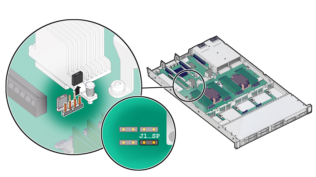
If installed, remove the jumper at location J1_SP on the new motherboard.

-
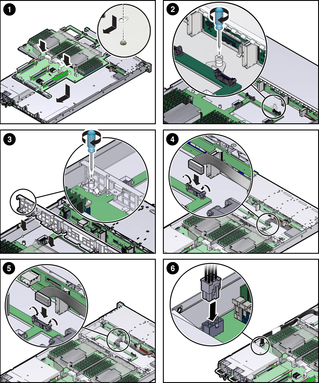
Insert the motherboard into the server chassis (1).

- Grasp the metal bracket located to the rear of the DIMMs and tilt the front of the motherboard up slightly and push it into the opening in the rear of the server chassis.
- Lower the motherboard into the server chassis and slide it to the rear until it engages the seven mushroom-shaped standoffs located on the server chassis under the motherboard.
- Ensure that the indicators, controls, and connectors on the rear of the motherboard fit correctly into the rear of the server chassis.
- Tighten the one green captive screw that secures the motherboard to the chassis (2).
-
Install the server mid-wall (3).
-
Place the SAS cables along the left chassis sidewall (viewing the
server form the front).
You will connect these cables to the internal HBA card later.
- Position the mid-wall over the front of the motherboard so that it engages the mushroom-shaped standoffs that are located on the server chassis sidewall (one for each end of the mid-wall).
- Ensure that SAS cables are not pinched by the mid-wall and that they run beside the mid-wall and not under it. Otherwise, the cables might be damaged.
- To secure the mid-wall to the server chassis, use a screwdriver (No. 2 Phillips or flathead) to tighten the four green captive screws.
-
Place the SAS cables along the left chassis sidewall (viewing the
server form the front).
-
If the server has a switch card, carefully guide card cables through the
chassis mid-wall.
You will connect these cables to the switch card later.
-
To install the FIM cable, push the side latches on the motherboard connector
to the open position and push the FIM cable connector in (4).
The side latches close, locking the connector in place.
- Reconnect the disk backplane Auxiliary power and signal cable to the motherboard (5).
- Reconnect the disk backplane power cable to the motherboard (6).
- Reinstall the air baffle.
-
Reinstall the following reusable components.
-
PCIe risers and attached PCIe cards.
See Servicing PCIe Cards.
- Power supplies.
-
Fan modules.
See Install a Fan Module.
-
PCIe risers and attached PCIe cards.
- Return the server to operation.
-
Update the system firmware.
See the Performing Firmware Updates section in the Oracle® ILOM Administrator's Guide for Configuration and Maintenance.
-
When you replace a motherboard that contains an SP, download the fallback
miniroot image for your hardware and your Oracle Solaris version from My Oracle
Support at https://support.oracle.com.
Then follow the procedure "Uploading a New Solaris Miniroot Package From SP to Host" in the Oracle ILOM Administrator's Guide for Configuration and Maintenance.