Indicator Blink Rates
This section describes the following indicator blink rates:
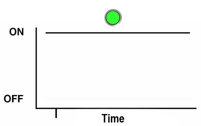
Steady On
For the steady on state, an indicator is continually on (lit) and does not blink. This indicates a continuing condition, for example, an operational state (green) or a Service Action Required fault state (amber).
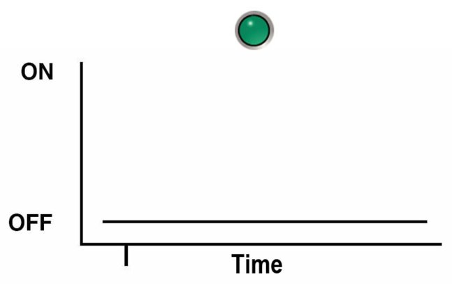
Steady Off
For the steady off state, an indicator is continually off (not lit) and does not blink. This indicates that a system is not operational, for example, no AC power (unlit green Power OK indicator) or a subsystem not in a fault state (unlit amber Service Action Required indicator).
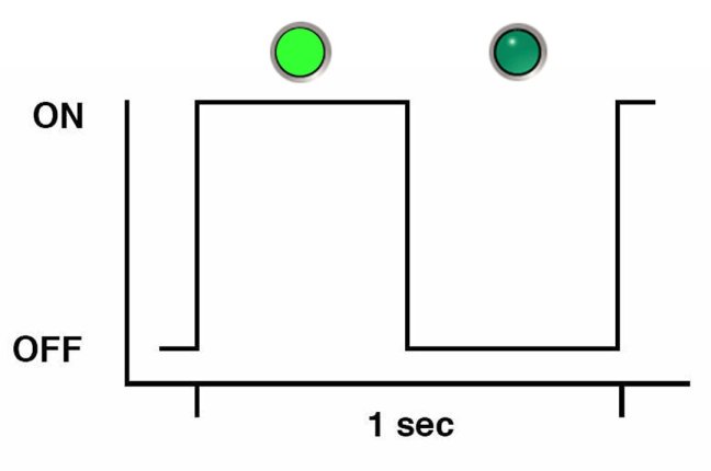
Slow Blink Rate
For the slow blink rate, the indicator (typically green) repeatedly lights for half a second during a one second interval (1 Hz) and turns off for half a second. The slow blink rate indicates an on-going activity. For example, device rebuilding, booting, or in transition from one mode to another.
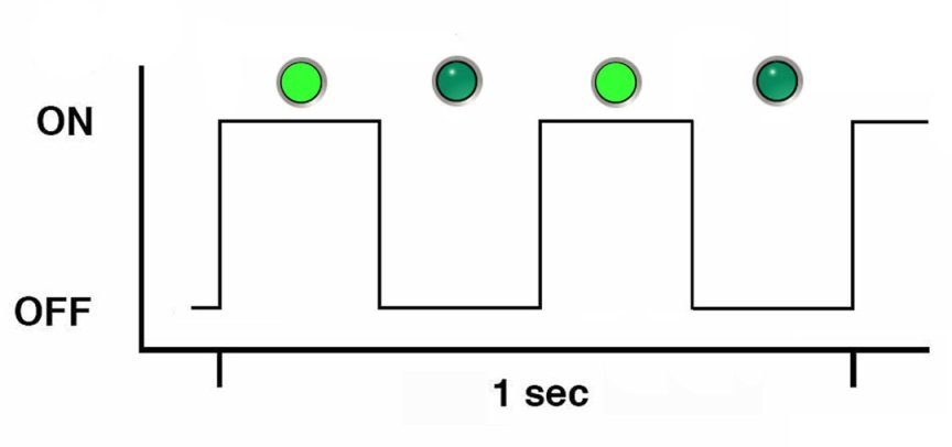
Fast Blink Rate
For the fast blink rate, the indicator repeatedly blinks twice (on, off, on) during a one second interval (2 Hz). The fast blink rate indicates activity or data transfer.
Single (Standby) Blink Rate
For the single blink rate, the indicator repeatedly flashes once at the beginning of a three second interval. This indicates a system or component in standby mode. For example, a server in standby power mode or a hot spare device waiting to be used (also used with amber indicators to indicate a predicted fault).
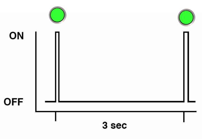
Slow Unison Blink Rate
For the slow unison blink rate, the indicators on the component blink in unison for half a second during a one second interval (1 Hz). Typically, this is limited to three successive blinks. This confirms the successful insertion of a removable device (for example, a storage drive) into a powered system (confirming the power connection).
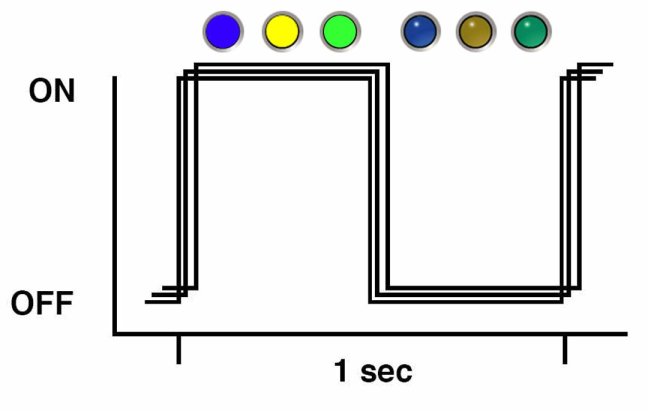
Insertion Blink
The insertion blink is three successive blinks of a hot-swap component's primary status indicator (for example, the green Power OK indicator). The insertion blink occurs immediately after three successive unison blinks (see Slow Unison Blink Rate) of all the component indicators.
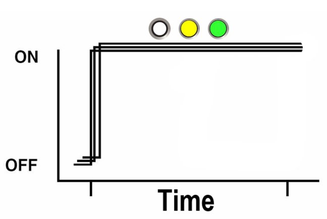
Unison Steady On
For the unison steady on, all indicators are simultaneously on steady (see Steady On. This occurs during the front panel lamp test (see Front Panel Lamp Test). This is the only time that the Locator indicator is on steady.
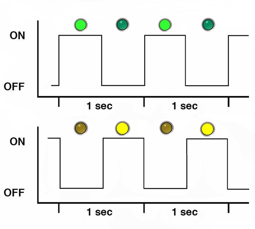
Alternating (Invalid FRU) Blink Rate
The alternating (invalid FRU) blink rate is a repeating sequence of lit green and amber indicators at 1 Hz. This indicates that a component has an incorrect version or mismatch (for example, a power supply with a lower rating than the one specified). The blink rate is also used for an unsupported component, or a component in an unsupported slot.
Feedback Flash
The indicator flashes on and off during periods of activity, commensurate with the activity, but the flashing does not exceed the 2 Hz fast blink rate (see, Fast Blink Rate). For example, this blink rate occurs during disk drive read and write activity and communication port transmit and receive activity.
Data Blink Rate
For this blink rate, a normally on Indicator repeatedly turns off twice during a one-second interval (2 Hz—see also, Fast Blink Rate) while data activity is taking place.
Sequential (Diagnostic) Blink Rate
This blink rate is a repeating sequence in which each indicator successively lights for 0.5 sec to indicate that diagnostics are running. This blink rate is used only on systems or components capable of running diagnostics.