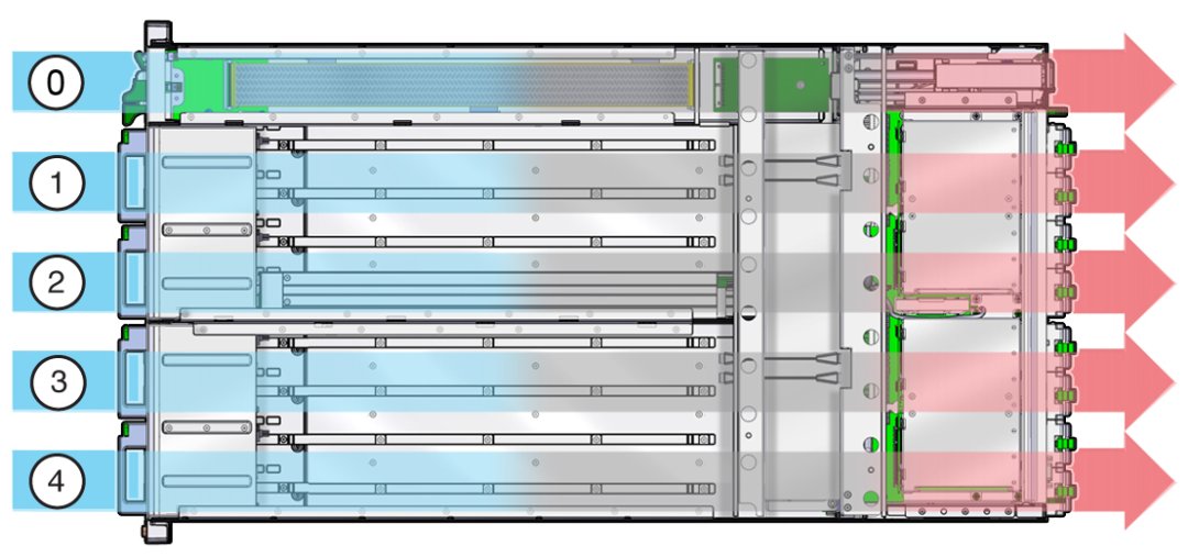
Chassis Cooling Subsystem
System cooling air flows from front to back. Primary cooling is provided by eight redundant front-side accessible 100 watt hot-swappable cooling fan modules. To maintain the integrity of the cooling system, ensure that:
-
All CMOD processors have a heat sink.
-
Each drive bay contains a storage device or a drive slot filler.
-
Every DPCC is installed regardless of whether it contains a card or not.
-
Both fan frames are populated with fan modules.
Cooling Zones
The server has five cooling zones. The cooling zones are designated from left to right (from the front of the server) as zone 0 - zone 4. The airflow cooling in zone 0 is concentrated through the power supplies (PSUs) and is provided by the internal PSU fan modules.
The fan modules (FMs) provide the airflow cooling for zones 1-4. Each zone has a pair of dedicated FMs:
-
Zone 1 airflow cooling is concentrated on the CPU modules (CMODs) 0 and 1 and is provided by FMs 0 and 1.
-
Zone 2 airflow cooling is concentrated on CMODs 2 and 3 and is provided by FMs 2 and 3.
-
Zone 3 airflow cooling is concentrated on CMODs 4 and 5 and is provided by FMs 4 and 5.
-
Zone 4 airflow is concentrated on CMODs 6 and 7 and is provided by FMs 6 and 7.
Note - In a four-CMOD configured server, the fan modules for cooling zones 3 and 4 are not powered. However, to maintain the integrity of the cooling subsystem, FMs 4-7 must be installed in the server.

|
Cooling Fan Power
Power for the internal PSU cooling fans (zone 0) is provided by the PSUs. Power for the fan modules (zones 1-4) is supplied by CMODs 0, 2, 4, and 6.
-
The chassis cooling fans operate only when the chassis is in full power mode (see Full Power Mode).
-
The PSU fans operate when the system is in full power or standby power mode.
The following table shows the CMODs and the fan modules to which they supply power:
|
Note - The fan power connectors for CMODs in slots 1,3,5, and 7 are not used.
Fan Module Redundancy
The eight fan modules (FMs) provide airflow for chassis cooling zones 1-4. For redundancy, each zone has two dedicated FMs. If an FM fails, replace it immediately. The FMs are hot-serviceable.
 | Caution - Data Loss. Do not remove more than one fan module from a column while the system is in full power mode. This action removes power from the CMODs and causes an immediate shutdown. On an eight-CMOD system, this applies to all fan modules. On a four-CMOD system, this applies to the fan modules in the left-hand fan frame. |
For FM reference and servicing information, see Servicing Fan Modules and Fan Frames.