Go to main content

Oracle® Server X5-8 Service Manual

Exit Print View

Updated: March 2018


Chassis Overview

The chassis consists of the front accessible components, internal components, and components accessible from the back of the server:

Chassis Front Side Components

The following figure shows the front side components:
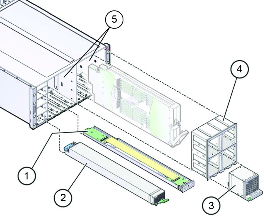
image:An illustration showing an exploded view of the chassis front-side                         components.

The front-side components include:

Call Out
Component
Link
1
Front indicator module (FIM)
2
Four power supplies
3 and 4
Eight fan modules (FMs) in two fan frames
5
Two internal CMOD bays

Chassis Internal Components

The following figure shows the chassis internal components:
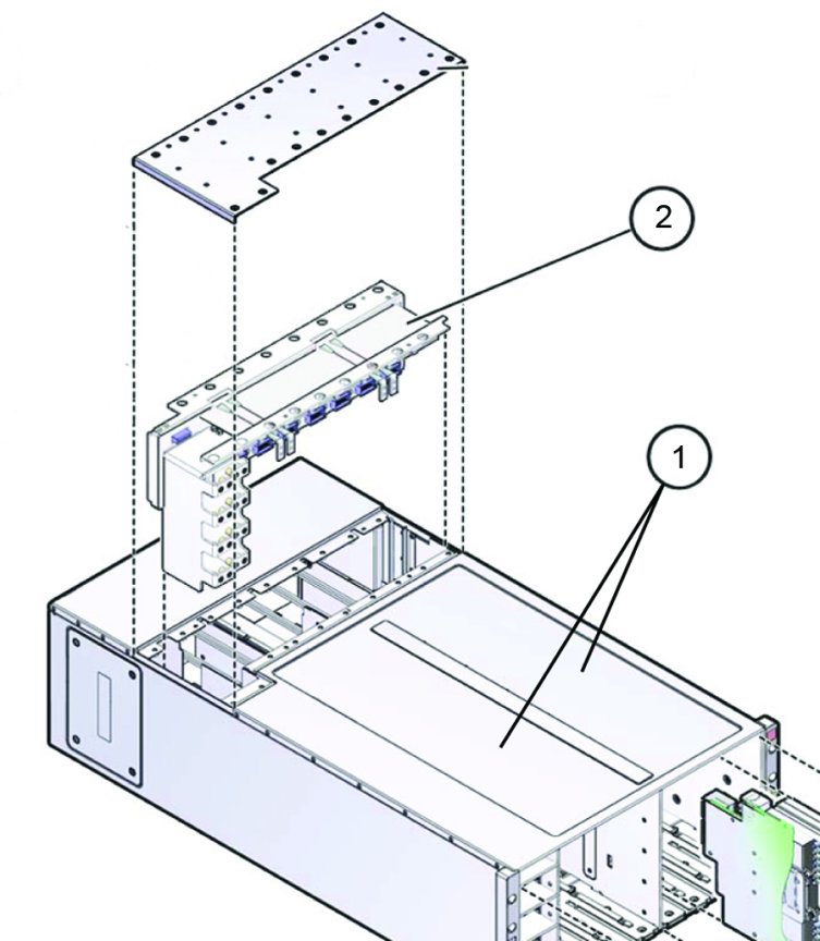
image:Picture of the chassis internal components.

The chassis internal components include:

Call Out
Component
Description
1
CPU module (CMOD) bays
CMOD bays can support either four or eight CMODs. Servicing CMODs requires warm or cold service.
For information about the CMODs, see CPU Module (CMOD) Overview.
2
Midplane/busbar
The mid-plane assembly provides an interconnect between the backside components and the front-side components. This component requires cold service.

Chassis Backside Components

The following figure shows the chassis backside components:
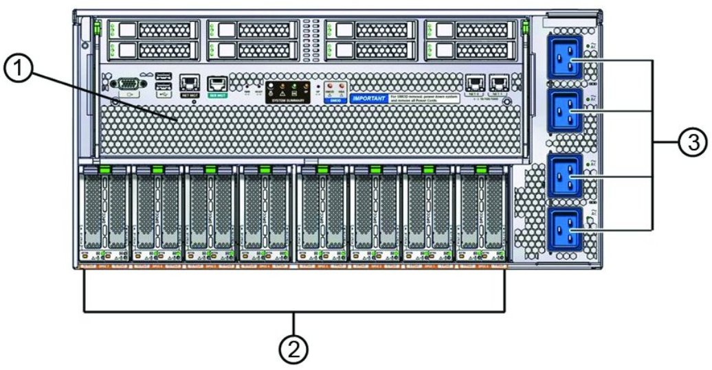
image:An illustration with call outs showing the chassis back                         components.

The chassis backside components include:

Call Out
Component
Description
1
System Module (SMOD)
The SMOD has internal components that can only be accessed by removing it from the backside of the server.
For more information, see System Module (SMOD) Overview.
2
Dual PCIe card carrier (DPCC) bay
The DPCC bay contains eight DPCCs and up to 16 PCIe cards.
For more information, see Storage and IO Subsystem.
3
AC power block
The AC power block has four AC power inlet connectors. The power block is not a removable component.
For more information, see Power Subsystem.