Install a Heatsink and Processor (FRU)
Before You Begin
-
For component information, see About System Components.
-
This procedure requires a Phillips screwdriver and an anti-static wrist strap.
-
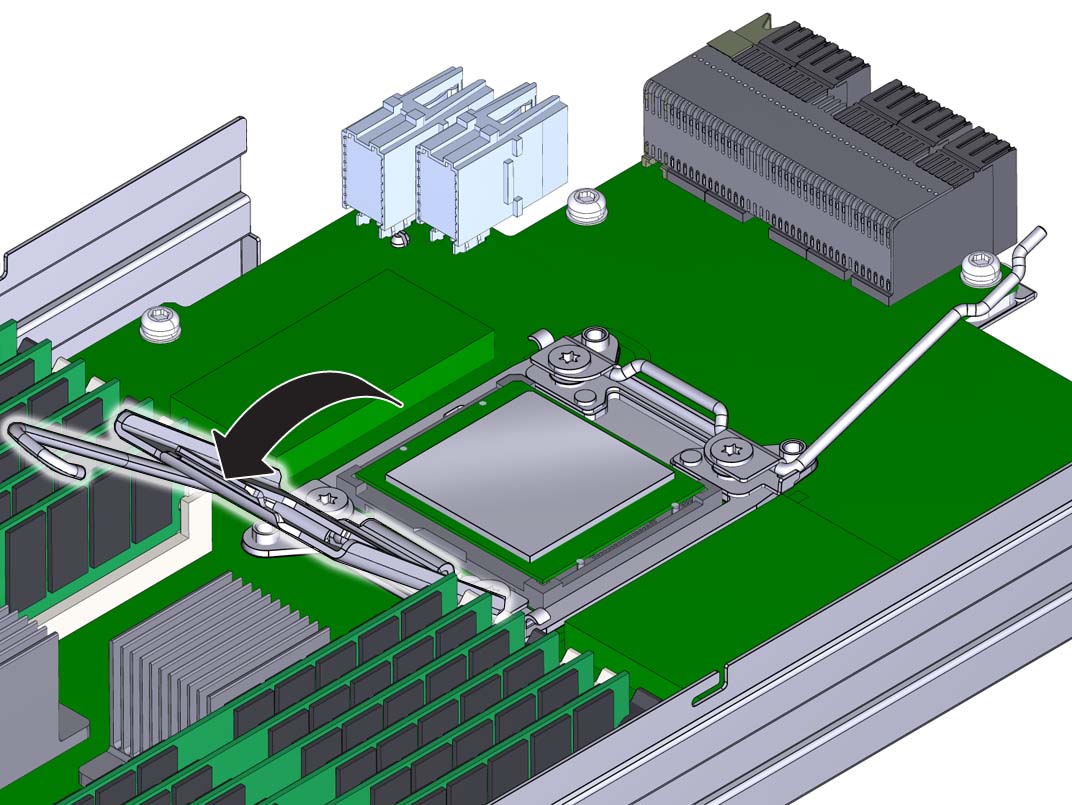
At the CPU socket, ensure that the CPU load plate and both load plate
release levers are in their fully open position.
-
To install a CPU, use the CPU replacement tool.
Note - Ensure that you use CPU replacement tool, part number 7080240. The part number is printed on the side of the tool. The tool is shipped with a new CPU.The tool is used to remove and install the CPU in the socket. The top side of the replacement tool has a button in the center and a tab on one side. Pressing down on the button opens the tool. Pressing the tab releases the button and closes the tool.
-
Press down on the release button on top of the replacement
tool.
This action opens the tool.
On one corner of the tool there is a label with a downward pointing triangle. Likewise, the CPU is marked with a triangle on one of its corners. This is a key that aids in correctly positioning the tool and the CPU with the CPU socket. The tool and the CPU are correctly positioned with the socket when all of the triangles are aligned.
- Turn the replacement tool upside down, noting the corner of the tool that is marked with a triangle (alignment key).
- Note the corner of the CPU that is marked with a triangle (alignment key).
- Lift the CPU by its edges, taking care not to touch the metal contacts on the underside of the CPU.
-
Turn the CPU upside down (metal contacts facing upward) and set it
on the replacement tool, ensuring that the triangle on the CPU
aligns with the triangle on the tool and that the CPU sits flat in
the tool. Do not release your hold the
CPU.
The CPU is not yet secured in the tool.
-
With the tool and the CPU in the topside down position, press the
topside release tab outward, away from the center button.
This action is accompanied by a click sound as the tool closes and grabs the CPU. The CPU should now be secured in the tool.
-
Ensure that the CPU is secured in the tool.
When the CPU is secured in the tool, there is no side-to-side movement of the CPU within the tool.
-
Press down on the release button on top of the replacement
tool.
-
Turn the tool over, so that the CPU contacts are facing downward.
This positions the tool with the topside facing upward.
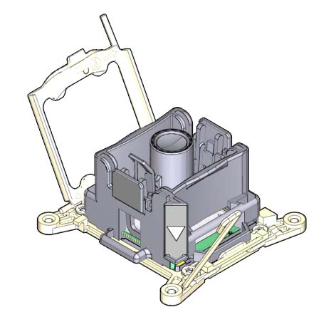
- Orient the tool so that the triangle on the tool aligns with the triangle on the socket.
-
Lower the tool onto the socket, ensuring that the CPU is correctly
positioned and sits flat and evenly in the socket.
When the CPU is correctly positioned, there is no side-to-side movement of the CPU within the socket.
-
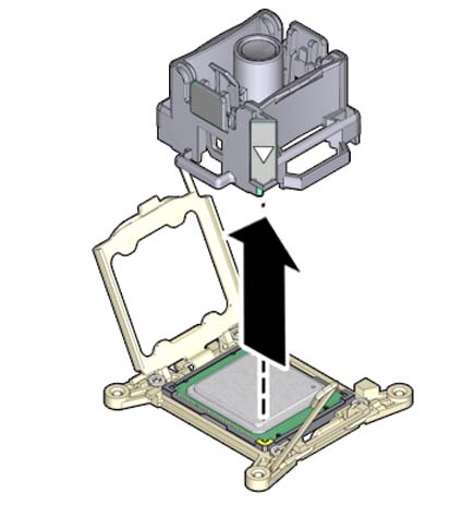
To release the CPU from the tool, press the center button.
This action is accompanied by a click sound as the tool opens and releases the CPU.
-
Remove the tool.
-
Inspect the CPU to ensure that it sits evenly within the socket.

Caution - Equipment Damage. Once the processor sits evenly in the socket, do not move it or push on it.
-
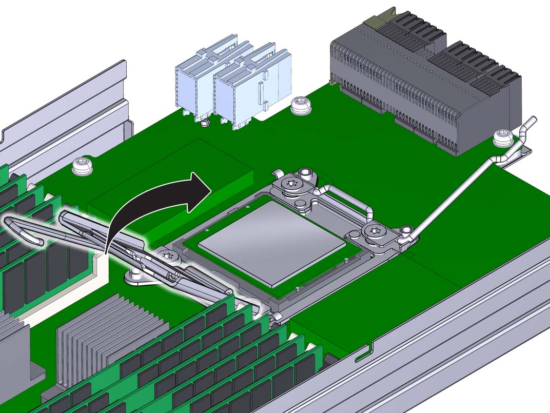
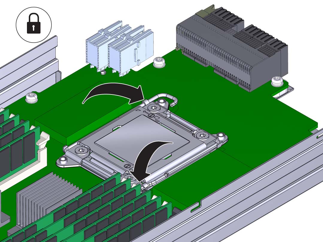
Close the CPU load plate.
-
Lower and lock the right side lever, ensuring that the lever is secured
under its retaining clip and that the bend in the lever locks the cover
plate.
The right side lever must be closed first.
-
Lower and lock the left side load plate lever, ensuring that it is secured
under its retaining clip.
-
To apply the thermal compound, dispense the contents of the syringe as a
single dollop in the center on the top of the CPU.
Do not spread the thermal compound. The pressure applied during the heatsink installation performs this action.
-
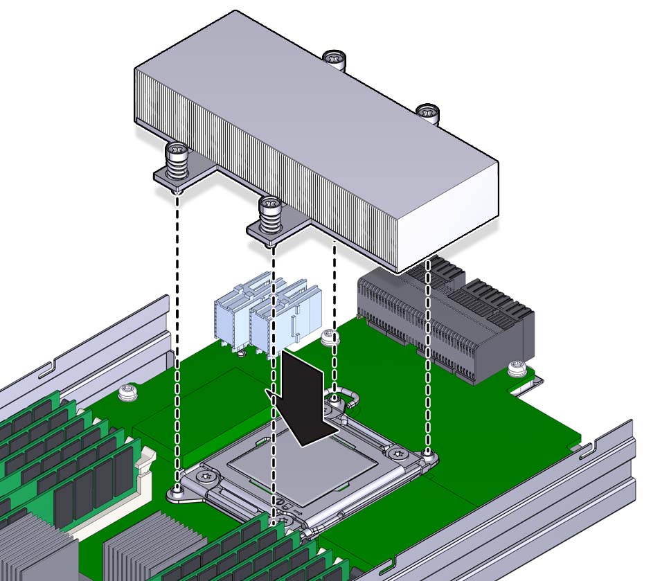
To install the heatsink:
-
Align the captive spring-loaded heatsink screws with the threaded
standoffs on the motherboard.
-
Set the heatsink on top of the CPU.
Once the heatsink is in contact with the CPU, avoid extra movement of the heatsink.
-
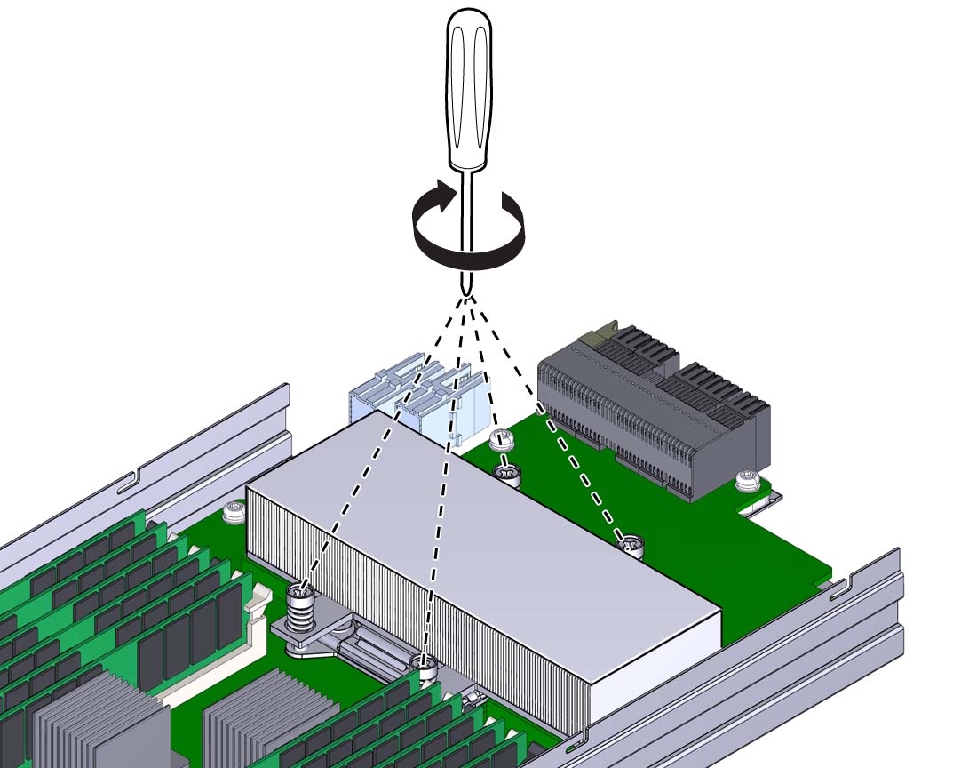
Use a number 2 Phillips screwdriver and alternately tighten each
screw one-half turn until both screws are completely
tightened.
-
Align the captive spring-loaded heatsink screws with the threaded
standoffs on the motherboard.
- Ensure that all tools and debris are removed from the CMOD.
-
Install the CMOD cover. See Remove and Install the CMOD Cover.
Note - After restoring service to the server, clear any related component faults. For more details, see Clear Hardware Fault Messages.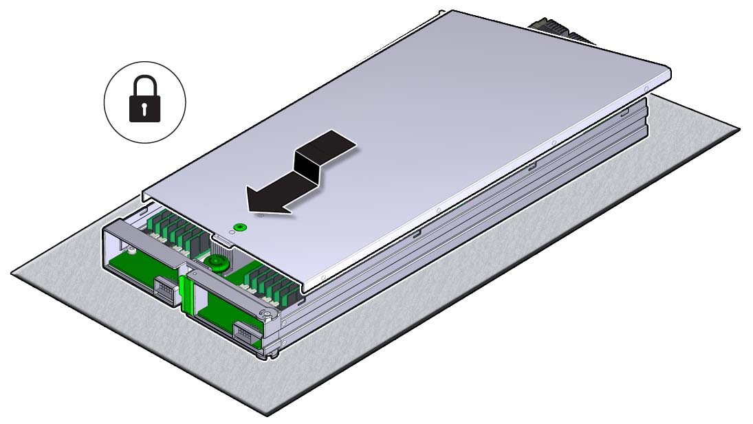
Next Steps