Go to main content

Oracle® Server X5-8 Service Manual

Exit Print View

Updated: March 2018


Illustrated Parts Breakdown

The following illustration shows the locations of the server components.
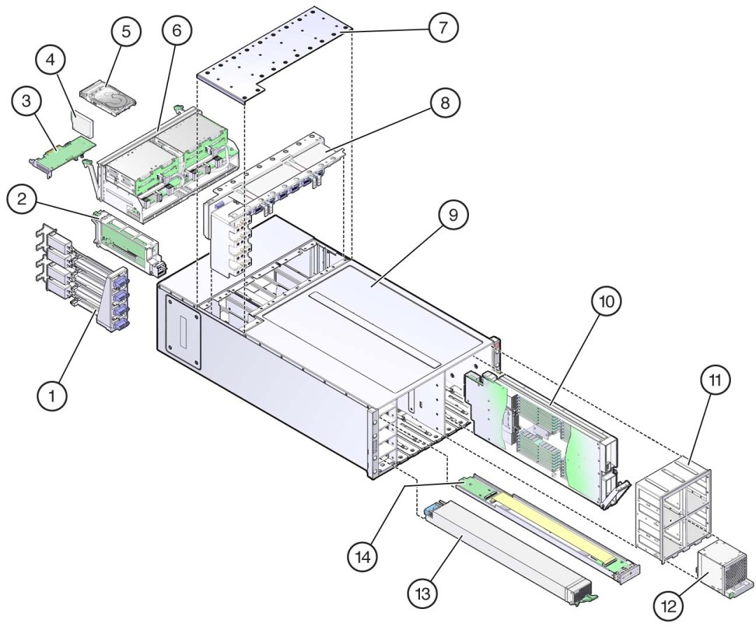
image:An illustration with call outs showing and exploded view of the server                         component locations.
Call Out
Description
Call Out
Description
1
AC power block

The AC power block is not a removable component.

8
Midplane
2
Dual PCIe carrier card (DPCC) with PCIe card (8)
9
Server chassis

The chassis is not a removable component.

3
Host bus adapter (HBA) card
10
CPU module (CMOD) (4 or 8)
4
Energy storage module
11
Fan frame (2)
5
Storage drive (8)
12
Fan module (8)
6
System module (SMOD)
13
Power supply (PSU) (4)
7
Top cover
14
Front indicator module (FIM)