Overview of ZS3-4 Controller
This section provides an overview of the Oracle ZFS Storage ZS3-4 controller. For installation instructions, refer to Installing a ZS4-4 or ZS3-4 Controller. For service instructions, refer to Servicing the ZS3-4 Controller in Oracle ZFS Storage Appliance Customer Service Manual.
ZS3-4 Electrical Specifications
The following list shows the electrical specifications for the ZS3-4 controller.
Note - The power dissipation numbers listed are the maximum rated power numbers for the power supply. The numbers are not a rating of the actual power consumption of the appliance.
Input
-
Nominal frequencies: 50/60Hz
-
AC operating range: 200-240 VAC
-
Maximum current AC RMS: 12A @ 200 VAC
Power Dissipation
-
Max power consumption: 1800 W
-
Max heat output: 6143 BTU/hr
-
Volt-Ampere rating: 1837 VA @ 240 VAC, 0.98 P.F.
ZS3-4 Configuration Options
The ZS3-4 controller can be configured as a single controller or two controllers to create a high-availability cluster configuration. The following table describes the configuration options:
|
Refer to http://oracle.com/zfsstorage for the most recent component specification.
ZS3-4 Front Panel Components
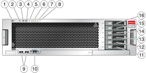
Figure 30 ZS3-4 Front Panel

| |||||||||||||||||||||
The ZS3-4 controller has two SAS-2 system boot drives in slots 0 and 1, configured as a mirrored pair. Up to four SAS-2 read cache SSDs can fill slots 2 through 5, in order. For information about supported HDDs and SSDs, see the Oracle Systems Handbook.
Figure 31 System Boot Drive LEDs

| ||||||
ZS3-4 Rear Panel Components
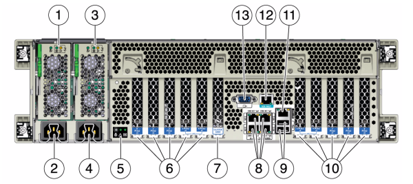
The following graphic shows the rear panel of the ZS3-4 controller. Base configuration HBAs are not depicted in this illustration.
For information about PCIe cards, see ZS3-4 PCIe I/O Cards in Oracle ZFS Storage Appliance Customer Service Manual.
Figure 32 ZS3-4 Rear Panel Components

| ||||||||||||||||||
-
Ethernet Ports - The ZS3-4 has four RJ-45 Gigabit Ethernet connectors (NET 0, NET 1, NET 2, NET 3) located on the motherboard that operate at 10/100/1000 Mbit/sec. These network interfaces must be configured before use.

-
Network Management Port - The network management connector (NET MGT) is an RJ-45 10/100 BASE-T Ethernet port and provides a LAN interface to the SP console.

-
Serial Management Port - The serial management connector (SER MGT) is an RJ-45 connector and provides a terminal connection to the SP console.

-
HBA Ports - The 4x4 SAS-2 HBA, installed in the ZS3-4, provides connectivity to external DE2 and Sun Disk Shelves. The HBA logical ports are numbered 3-0, top to bottom:
