Illustrated Parts Breakdown
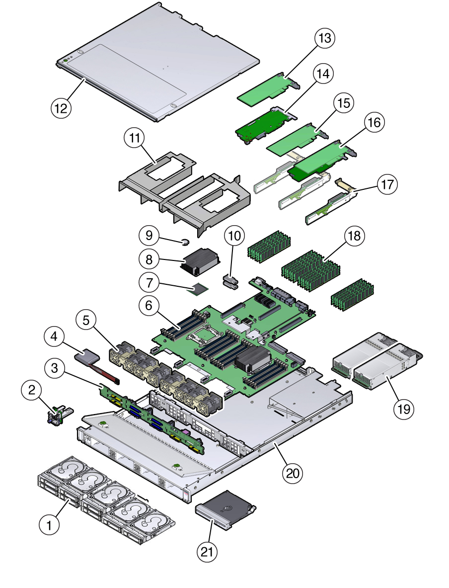
The following figure identifies the major components of the server.
Figure 1 Server Illustrated Parts Breakdown

|
|
|
1
|
Storage drives
|
|
2
|
Front indicator module (FIM)
|
|
3
|
Disk backplane
|
|
4
|
Super capacitor (Energy storage module for the Oracle Storage
12 Gb/s SAS PCIe RAID HBA in PCIe slot 4.)
|
|
5
|
Fan modules
|
|
6
|
Motherboard
|
|
7
|
Processors
Note -
In single-processor systems, neither a heatsink nor a
processor socket filler are installed in the processor
socket 1 (P1). To protect the delicate processor socket
pins, the cover that comes on the motherboard from
manufacturing is left in place.
|
|
8
|
Heatsinks
|
|
9
|
Battery
|
|
10
|
USB flash drives (One of the USB flash drives is used for
Oracle System Assistant.)
|
|
11
|
Air baffle
|
|
12
|
Top cover
|
|
13
|
(Optional) PCIe card in slot 3
|
|
14
|
Oracle Storage 12 Gb/s SAS PCIe RAID HBA card in PCIe slot
4
|
|
15
|
(Optional) PCIe card in slot 2
|
|
16
|
(Optional) Oracle PCIe NVMe switch card or standard PCIe card
in slot 1
Note -
PCIe slot 1 is nonfunctional in single-processor
systems.
|
|
17
|
PCIe risers (3)
|
|
18
|
DIMMs
Note -
A maximum of 12 DIMMs are supported in single-processor
systems and the DIMMs must be installed in sockets
associated with processor 0 (P0). No DIMM filler panels are
required in vacant DIMM sockets associated with processors 0
(P0) or 1 (P1).
|
|
19
|
Power supplies
|
|
20
|
Server chassis
|
|
21
|
(Optional) DVD drive
|
|

