Remove a Processor
 | Caution - Processors should be removed only by authorized Oracle Services personnel. |
 | Caution - Processor removal and replacement must be done using the removal and replacement tool that is included with the replacement processor for the server (see Selecting the Correct Processor Removal and Replacement Tool). Using a tool with a different color code might result in damage to the processor and processor socket. |
- Prepare the server for service.
-
If the server has a DVD drive, disconnect the DVD cable from the disk
backplane, carefully pull it through the chassis mid-wall, and move it to
the side away from of the air baffle.
For instructions for disconnecting the DVD cable from the disk backplane, see Servicing the Power, FIM, Disk Backplane Data, and DVD Cables.
-
If the server has an Oracle PCIe NVMe switch card installed, disconnect
the switch card cables from the disk backplane, carefully pull them through
the chassis mid-wall, and move them to side away from the air baffle.
For instructions for disconnecting the switch card cables from the disk backplane, see Servicing the NVMe Cables.
- Lift the air baffle up and out of the server and put it aside.
-
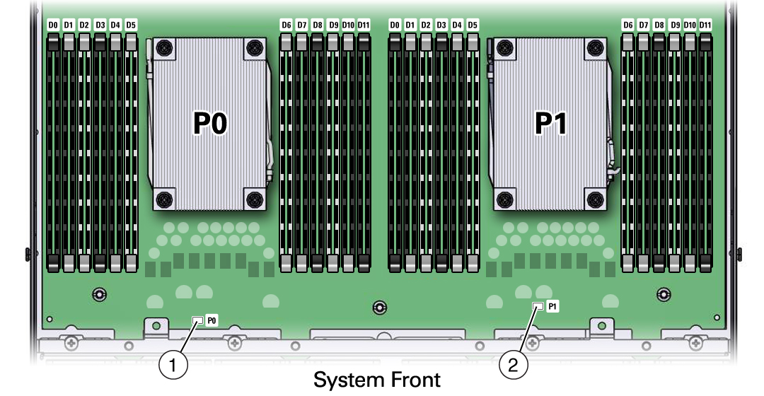
Identify the
location of the failed processor by pressing the Fault Remind
button on the motherboard.
Note - When the Fault Remind button is pressed, a LED located next to the Fault Remind button lights green to indicate that there is sufficient voltage present in the fault remind circuit to light any fault LEDs that were lit due to a failure. If this LED fails to light when you press the Fault Remind button, it is likely that the capacitor powering the fault remind circuit has lost its charge. This can happen if the Fault Remind button is pressed for a long time with fault LEDs lit or if power has been removed from the server for more than 15 minutes.The processor fault LEDs are located next to the processor(s).
-
If the processor fault LED is off, then the processor is operating properly.
-
If the processor fault LED is on (amber), then the processor is failed and should be replaced.
 NumberDescription1Processor 0 (P0) fault LED2Processor 1 (P1) fault LED
 -
-
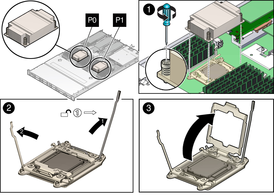
Gently press down on the top of the heatsink to counteract the pressure of
the captive spring-loaded screws that secure the heatsink to the motherboard
and loosen the four Phillips captive screws in the heatsink for the failed
processor [1].

Using a No. 2 Phillips screwdriver, turn the screws counterclockwise alternately one and one half turns until they are fully removed.
-
To separate the heatsink from the top of the processor, gently twist the
heatsink left and right, while pulling upward, and then lift off the
heatsink and place it upside down on a flat surface [1].
A thin layer of thermal grease separates the heatsink and the processor. This grease acts as an adhesive.
Note - Do not allow the thermal grease to contaminate the work space or other components. -
Use an alcohol pad to clean the thermal grease from the underside of the
heatsink.
Be very careful not to get the thermal grease on your fingers.

Caution - Failure to clean the heatsink prior to removing the processor could result in the accidental contamination of the processor socket or other components. Also, be careful not to get the grease on your fingers as this could result in contamination of components.
- Disengage the processor release lever on the right side of the processor socket (viewing the server from the front) by pushing down on the lever and moving it to the side away from the processor, and then rotating the lever upward [2].
- Disengage the processor release lever on the left side of the processor socket (viewing the server from the front) by pushing down on the lever and moving it to the side away from the processor, and then rotating the lever upward [2].
-
To lift the ILM assembly load plate off of the processor socket, rotate
the processor release lever on the right side of the processor toward the
closed position (the ILM assembly load plate is lifted up as the release
lever is lowered toward the closed position) and carefully swing the ILM
load plate to the fully open position [3].

Caution - Whenever you remove a processor, you should replace it with another processor and reinstall the processor heatsink; otherwise, the server might overheat due to improper airflow. For instructions for installing a processor, see Install a Processor.
-
To remove the processor from the processor socket, acquire the processor
removal and replacement tool and perform the following steps:
Caution - Before removing the processor, ensure that you are using the correct color-coded processor removal and replacement tool. For information on how to select the correct processor removal and replacement tool, see "Selecting the Correct Processor removal and replacement Tool" on page 106.
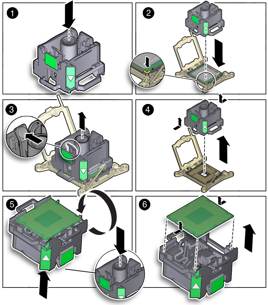
- Locate the button in the center of the top of the processor removal and replacement tool and press it to the down position [1].
-
Properly position the tool over the processor socket and lower it
into place over the processor socket [2].
To properly position the tool over the processor socket, rotate the tool until the green triangle on the side of the tool is facing the front of the server and it is over the left side of the processor socket when viewing the server from the front.
-
Press the release lever on the tool to release the center button
and engage the processor [3].
An audible click indicates that the processor is engaged.
- Grasp the tool by the sides and remove it from the server [4].
- Turn the tool upside down and verify that it contains the processor [5].
- While holding the processor tool up side down, press the center button on the tool to release the processor [5].
- Carefully grasp the processor by the front and back edges, lift it out of the tool and place it with the circuit side down (the installed orientation) into an antistatic container [6].
-
Carefully clean the thermal grease off the top of the
processor.
Caution - The following figure shows the green color-coded processor removal and replacement tool. If you are removing a 12-core processor, you must use the pink color-coded processor removal and replacement tool; otherwise, damage might result to the processor or the processor socket. For information on how to select the correct processor removal and replacement tool, see "Selecting the Correct Processor removal and replacement Tool" on page 106.
