JavaScript is required to for searching.
Skip Navigation Links
Exit Print View
Sun Network QDR InfiniBand Gateway Switch HTML Document Collection for Firmware Version 2.1
search filter icon
search icon

Document Information

Using This Documentation

Product Notes

Related Documentation

Feedback

Access to Oracle Support

Installation

Understanding the Gateway

Gateway Overview

Physical Specifications

Environmental Requirements

Acoustic Noise Emissions

Electrical Specifications

NET MGT Connector and Pins

USB Management Connector and Pins

Data QSFP Connector and Pins

Understanding Cabling

Routing Service Cables

Understanding Data Cabling

Preparing to Install the Gateway

Installation Preparation

Suggested Tools for Installation

Antistatic Precautions for Installation

Installation Responsibilities

Installation Sequence

Verify Shipping Carton Contents

Assemble the Optical Fiber Data Cables

Route the Data Cables

Installing the Gateway

Install the Gateway in the Rack

Powering On the Gateway

Attach the Management Cables

Attach the Power Cords

Accessing the Management Controller

Access the Management Controller From the NET MGT Port

Access the Management Controller From the USB Management Port

Verify the Gateway Status

Start the Subnet Manager

Connecting Data cables

Attach the Data Cables

Check Link Status

Verifying the InfiniBand Fabric

InfiniBand Node Description

Discover the InfiniBand Fabric Topology

Perform Diagnostics on the InfiniBand Fabric

Administration

Troubleshooting the Gateway

Gateway Hardware Problems

InfiniBand Fabric Problems

Network Management Troubleshooting Guidelines

Understanding Routing Through the Gateway

Switch GUIDs Overview

Understanding Administrative Commands

Configuration Overview

Oracle ILOM Command Overview

Hardware Command Overview

InfiniBand Command Overview

Administering the Chassis

Monitoring the Chassis

Controlling the Chassis

Administering the I4 Switch Chip

Monitoring the I4 Switch Chip

Controlling the I4 Switch Chip

Administering the Subnet Manager

Monitoring the Subnet Manager

Controlling the Subnet Manager

Configuring Secure Fabric Management

Administering the InfiniBand Fabric

Monitoring the InfiniBand Fabric

Controlling the InfiniBand Fabric

Administering Gateway Resources

Installing Gateway Supportive Software (Linux)

Creating VNICs Under Gateway Manual Mode (Linux)

Creating VNICs Under Host Manual Mode (Linux)

Creating Virtual IO Adapters (Oracle Solaris)

Monitoring Gateway Resources

Controlling LAGs

Controlling VLANs and VNICs

Controlling Gateway Ports and Parameters

Remote Management

Understanding Oracle ILOM on the Gateway

Oracle ILOM Overview

Supported Features

Understanding Oracle ILOM Targets

Administering Oracle ILOM (CLI)

CLI Overview

Accessing Oracle ILOM From the CLI

Switching Between the Oracle ILOM Shell and the Linux Shell

Monitoring Oracle ILOM Targets (CLI)

Controlling Oracle ILOM Targets (CLI)

Upgrading the Gateway Firmware Through Oracle ILOM (CLI)

Administering Oracle ILOM (Web)

Web Interface Overview

Access Oracle ILOM From the Web Interface

Monitoring Oracle ILOM Targets (Web)

Controlling Oracle ILOM Targets (Web)

Upgrade the Gateway Firmware (Web)

Using the Fabric Monitor

Access the Fabric Monitor

Fabric Monitor Features

Accessing the Rear Panel Diagram

Accessing Status Pane Information

Control Panel Function

Monitoring Parameters and Status

Administering Oracle ILOM (SNMP)

SNMP Overview

Understanding SNMP Commands

Monitoring Oracle ILOM Targets (SNMP)

Controlling Oracle ILOM Targets (SNMP)

Administering Hardware (IPMI)

ipmitool Overview

Display the Sensor States (IPMI)

Display the Sensor Information (IPMI)

Display the System Event Log (IPMI)

Display FRU ID Information (IPMI)

Display Gateway Status LED States (IPMI)

Enable the Locator LED (IPMI)

Disable the Locator LED (IPMI)

Understanding Oracle ILOM Commands

cd Command

create Command

delete Command

dump Command

exit Command (Oracle ILOM)

help Command (Oracle ILOM)

load Command

reset Command

set Command

show Command

version Command (Oracle ILOM)

Service

Detecting and Managing Faults

Interpreting Status LEDs

Managing Faulty Components

Identify Faults in the Oracle ILOM Event Log

Determining the Alarm State of a Component or System

Evaluating Sensor Alarms

Accessing CLI Prompts

Understanding Service Procedures

Replaceable Components

Suggested Tools for Service

Antistatic Precautions for Service

Servicing Power Supplies

Determine If a Power Supply Is Faulty

Inspecting a Power Supply

Power Off a Power Supply

Remove a Power Supply

Install a Power Supply

Power On a Power Supply

Servicing Fans

Determine If a Fan Is Faulty

Inspecting a Fan

Remove a Fan

Install a Fan

Servicing Data Cables

Inspecting the Data Cables

Remove a Data Cable

Install a Data Cable

Servicing the Battery

Determine If the Battery Is Faulty

Remove the Gateway From the Rack

Replace the Battery

Reference

Understanding Hardware Commands

Linux Shells for Hardware Commands

addlagport Command

allowhostconfig Command

autodisable Command

checkboot Command

checkpower Command

checktopomax Command

checkvoltages Command

connector Command

create_ipoib Command

createfabric Command

createlag Command

createvlan Command

createvnic Command

dcsport Command

delete_ipoib Command

deletelag Command

deletevlan Command

deletevnic Command

dellagport Command

disablecablelog Command

disablegwport Command

disablelagmode Command

disablelinklog Command

disablesm Command

disableswitchport Command

disablevnic Command

disallowhostconfig Command

enablecablelog Command

enablegwport Command

enablelagmode Command

enablelinklog Command

enablesm Command

enableswitchport Command

enablevnic Command

env_test Command

exit Command (Hardware)

fdconfig Command

fwverify Command

generatetopology Command

getfanspeed Command

getmaster Command

getportcounters Command

getportstatus Command

help Command (Hardware)

listlinkup Command

localmkeypersistence Command

matchtopology Command

modifyvnic Command

setcontrolledhandover Command

setdefaultgwdiscpkey Command

setgwethport Command

setgwinstance Command

setgwsl Command

setgwsystemname Command

sethostvniclimit Command

setmsmlocationmonitor Command

setsmmkey Command

setsmpriority Command

setsmrouting Command

setsubnetprefix Command

showdisk Command

showfree Command

showfruinfo Command

showgwconfig Command

showgwports Command

showioadapters Command

showlag Command

showpsufru Command

showsmlog Command

showtemps Command

showtopology Command

showunhealthy Command

showvlan Command

showvnics Command

smconfigtest Command

smnodes Command

smpartition Command

smsubnetprotection Command

version Command (Hardware)

Understanding InfiniBand Commands

Linux Shells for InfiniBand Commands

ibdiagnet Command

ibhosts Command

ibnetdiscover Command

ibnetstatus Command

ibnodes Command

ibportstate Command

ibroute Command

ibrouters Command

ibstat Command

ibswitches Command

ibtracert Command

perfquery Command

saquery Command

smpquery Command

Understanding SNMP MIB OIDs

OID Tables Overview

Understanding the SUN-DCS-IB-MIB MIB OIDs

Understanding the SUN-FABRIC-MIB MIB OIDs

Understanding the SUN-HW-TRAP-MIB MIB OIDs

Understanding the SUN-ILOM-CONTROL-MIB MIB OIDs

Understanding the SUN-PLATFORM-MIB MIB OIDs

Understanding the ENTITY-MIB MIB OIDs

Index

Attach the Power Cords

The power cords for the gateway ship separately and are specific to the country of installation. See Power Cord Requirements. The facility power receptacles for the power cords should be located such that the power cords are routed out of the way, either to the sides of the rack or under the floor.

When live power is delivered to the receptacles at the rear of the chassis, standby and main power is made available by the power supplies. When standby power is distributed to the chassis, the management controller is powered on. The main power is supplied for the switch chip and fans.
  1. Identify the prerequisite and subsequent installation tasks that you must perform in conjunction with this procedure.

    See Installation Sequence.

  2. Ensure that the circuit breakers for the facility power are switched off.
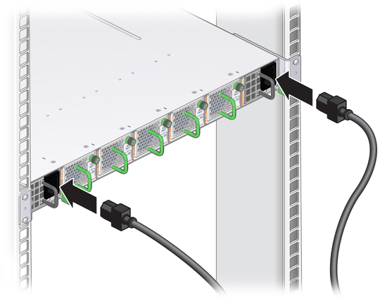
  3. Plug the power cords into the receptacles at the front of the gateway chassis.
    image:Illustration shows the power cords being attached.
  4. Route the end of each power cord to its respective facility power receptacle.

    Use cable ties or hook and loop fastener straps to bundle and secure the cord.

  5. Plug each power cord into the receptacle.

    Note - To provide redundancy, connect each power cord to a separate power source. The gateway can operate with only one power source, but there is no redundancy in that case.


  6. Energize the circuit breakers so that the power receptacles are live.
  7. Verify that the status LEDs for each power supply indicate normal operation.

    The AC LED on each power supply lights green. A moment later, the OK LED lights green. The Attention LED should be unlit. Refer to Gateway Service, checking power supply status LEDs.

    • If the AC LED does not light, there is something wrong with supplied power.

    • If the OK LED does not light, there is something wrong with the power supply.

    • If the Attention LED on a power supply lights, there is a fault in the power supply.

    • If the Attention LED on a fan lights, there is a fault with that fan.


    Note - At this time, power is being supplied to the management controller. The controller is effectively on and booting up. You might see the boot sequence on the management console.


  8. Verify that the fans spin up.

    You should feel air going into the fans, and the fan Attention LEDs should be unlit. Refer to Gateway Service, checking fan status LEDs.

  9. Verify that the chassis status OK LED lights.

    Refer to Gateway Service, checking chassis status LEDs.

  10. Access the management controller.

    See Accessing the Management Controller.

Related Information