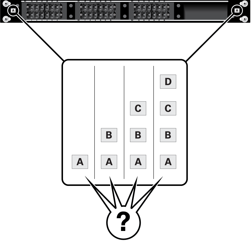
Identifying MPO Coupler Panel Ports
MPO couplers can be installed instead of the Oracle Switch ES2-72 group. MPO couplers cannot be combined with fiber switches in the four slots designated for either a switch group or an MPO group.
Up to four MPO coupler panels can be installed, based on node configurations and connectivity per node.
-
Panel letter designations A, B, C, or D correspond to the PMT-x interfaces on the node blind-mate interface (VFI connector) at the FBS.
-
Each node supports up to 4 PMT connections (each one a 12-fiber optic interface).
-
Each panel (A, B, C or D) connects to the corresponding PMT-x connection on a node. For example, 30 of the ports on panel A connect to 30 FBS interfaces at PMT-A, respectively.
-
The panel port number connects to the FBS at the corresponding RU location (slot). For example:
-
Port 8 on panel A connects to FBS PMT-A at slot 8.
-
Port 8 on panel B connects to FBS PMT-B at slot 8.
-
Port 3 on panel A connects to port A on the FBS at slot 3.
-
Port 17 on panel C connects to port C on the FBS at slot 17.
Note - You can connect compatible external technology to match what is on the FBA port A at slot 3 and on the FBA port C at slot 17, as well as all any of the other ports on the MPO panels.
-
-
Each panel is technology independent, and the type of data available at each panel's port is dependent upon the node configuration.
-
Depending on the node type and PCIe card configuration, the fiber I/O cards map to the FBS/FBA ports A, B, C, and D.
