JavaScript is required to for searching.
Skip Navigation Links
Exit Print View
Sun Datacenter InfiniBand Switch 648 Topic Set
search filter icon
search icon

Document Information

Preface

Related Documentation

Documentation, Support, and Training

Third-Party Web Sites

Sun Welcomes Your Comments

Administration

Administering the Switch

Understanding Administrative Commands

Monitoring the Switch

Monitoring the InfiniBand Fabric

Controlling the Switch

Controlling the InfiniBand Fabric

Diagnosing a Problem

Identifying the Problem

Troubleshooting the Switch

Understanding Signal Routing Through the Switch

Understanding Switch Startup and Component Addition

Switch GUIDs Overview

Remote Management

Understanding ILOM on the Switch

ILOM Documentation

ILOM Overview

Supported Features

Understanding ILOM Targets

Installing the ILOM Firmware

Firmware Layout

rupgrade_tool Application

Download the ILOM Firmware

Install the ILOM Firmware

Administering ILOM (CLI)

CLI Overview

Access ILOM From the CLI

Switching Between the ILOM Shell and the Linux Shell

Monitoring ILOM Targets (CLI)

Controlling ILOM Targets (CLI)

Upgrading the Switch Firmware Through ILOM (CLI)

Administering ILOM (Web Interface)

Web Interface Overview

Access ILOM From the Web Interface

Monitoring ILOM Targets (Web Interface)

Controlling ILOM Targets (Web Interface)

Upgrading the Switch Firmware Through ILOM (Web Interface)

Understanding ILOM Commands

cd Command

create Command

delete Command

dump Command

exit Command

help Command

load Command

set Command

show Command

version Command

Installation

Preparing the Site

Routing Service Cables

Understanding InfiniBand Cabling

Understanding Switch Specifications

Installing the Switch

Understanding the Installation

Installing the InfiniBand Software Stack

Unpacking the Chassis

Preparing the Chassis

Inspecting the Components

Installing the Components

Powering On the CMCs

Powering On the Fabric Cards

Powering On the Line Cards

Connecting InfiniBand Cables

Verifying the InfiniBand Fabric

Service

Servicing the Switch

Understanding Service Procedures

Antistatic Precautions

Suggested Tools

Component Addressing

Connector Addressing

Replaceable Components

Servicing the Power Supplies

Inspecting the Power Supplies

Power Supply Identification

Inspect the Power Supply Hardware

Inspect the Power Supply Connectors

Power Off a Power Supply

Remove a Power Supply

Install a Power Supply

Power On a Power Supply

Servicing the CMCs

Inspecting the CMC

CMC Identification

Inspect the CMC Hardware

Inspect the CMC Connectors

Power Off a CMC

Remove a CMC

Install a CMC

Power On a CMC

Servicing the Fans

Inspecting the Fans

Fan Identification

Inspect the Fan Hardware

Inspect the Fan Connector

Remove a Fan

Install a Fan

Servicing the Fabric Cards and Fabric Card Fillers

Inspecting the Fabric Cards

Fabric Card Identification

Inspect the Fabric Card Chassis

Inspect the Fabric Card Retainer Bolts

Inspect the Fabric Card Fans

Inspect the Fabric Card XBOW Connectors

Power Off a Fabric Card

Remove a Fabric Card or Fabric Card Filler

Install a Fabric Card or Fabric Card Filler

Power On a Fabric Card

Servicing the InfiniBand Cables

Inspecting the InfiniBand Cables

InfiniBand Cable Identification

Inspect the InfiniBand Cable Hardware

Inspect the InfiniBand Cable Connectors

Remove an InfiniBand Cable

Install an InfiniBand Cable

Servicing the Line Cards

Inspecting the Line Cards

Line Card Identification

Inspect the Line Card Chassis

Inspect the Line Card Retainer Bolts

Inspect the Line Card XBOW Connectors

Inspect the Line Card CXP Connectors

Power Off a Line Card

Remove a Line Card

Install a Line Card Filler

Remove a Line Card Filler

Install a Line Card

Power On a Line Card

Doing Supportive Software Tasks

Reperform Initial Setup

Configure CMCs for Identical Addresses

Upgrading the Firmware

Set Up a TFTP Server

Reference

Command Reference

Understanding Switch-Specific Commands

Understanding CLIA Commands

Understanding InfiniBand Software Commands

Index

Install an InfiniBand Cable


Note - “A” cables stack on top of “B” cables. For example, the cable for 5A will stack on top of the cable for 5B.


  1. Identify the prerequisite and subsequent tasks you must perform in conjunction with this procedure, to achieve a goal.

    See the table in Servicing the InfiniBand Cables.
  2. Consider your next steps:
    • If you are cabling an entire line card after a replacement procedure, go to Step 3.
    • If you are installing a replacement cable to the switch, go to Step 5.
  3. Locate the cable for the connector 0B.
  4. Go to Step 9.
  5. Inspect the replacement InfiniBand cable.

    See Inspecting the InfiniBand Cables.

  6. Bring the replacement cable to the switch.
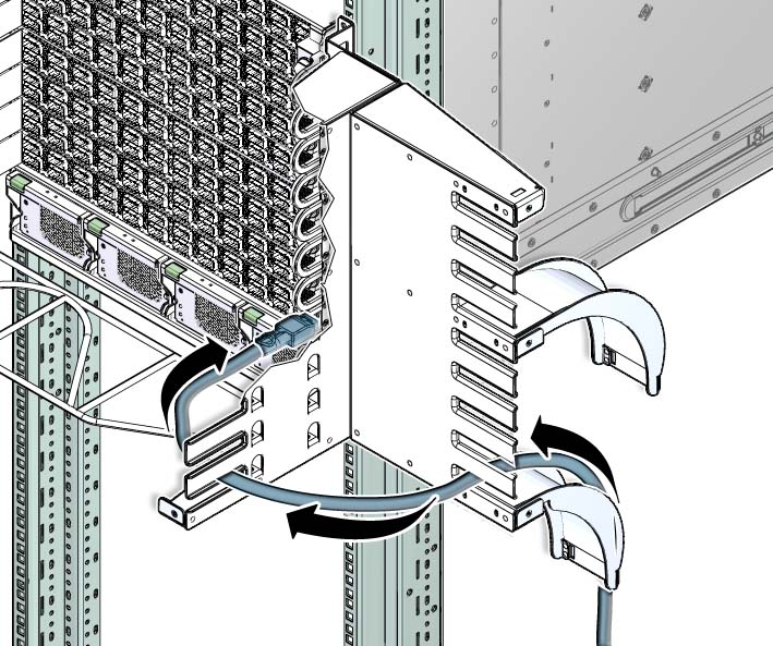
  7. Lay the cable over the cable curve.
  8. Feed the cable through the side branch of the cable tree.
    Illustration shows an InfiniBand cable being threaded through the cable tree.
  9. Curve the cable through the main trunk of the cable tree.

    Caution

    Caution - Do not allow any copper core InfiniBand cable to bend tighter than a 5 inch (127 mm) radius. Do not allow any optical InfiniBand cable to bend tighter than a 3.4 inch (85 mm) radius. Tight bends can damage the cable internally.


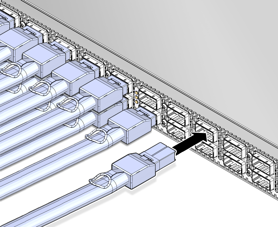
  10. Plug the cable into the appropriate connector.
    Illustration shows an InfiniBand cable being connected.
    1. Visually inspect the cable connector to see whether the shell is not bent and is parallel to the inner boards.

      If the shell is bent or damaged, get a different cable.

    2. Ensure that the retraction strap is forward.
    3. Orient the cable connector to horizontal.

      Ensure that the upper shell just touches the underside of the top of the receptacle on the line card.
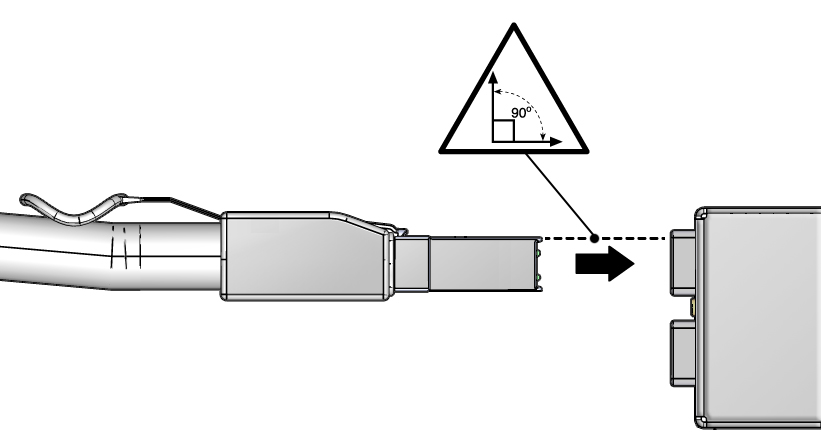

      Illustration shows an InfiniBand cable being aligned.
    4. Slowly move the connector in.

      As you slide the connector in, the top of the shell should scrape against the underside of the top of the receptacle on the line card.

      • If the cable stops or binds after about 5 mm (1/4 in.) travel, back out and repeat Step c and Step d.
      • If the connector stops or binds with about 2 mm (1/8 in.) still to go, back out and repeat Step c and Step d.
    5. Continue to push the connector in until the hooks catch onto the top of the connector on the line card.
  11. Consider your next step:
    • If you are replacing a cable at connectors 6A through 11B, repeat Step 8 through Step 10, moving to the left, working your way to connector 6A.

      For example, if you are replacing cable 9A, install 9A, 8B, 8A, 7B, and so on to 6B and 6A.

    • If you are replacing a cable at connectors 0A through 5B, repeat Step 8 through Step 10, moving to the right, working your way to connector 5B.

      For example, if you are replacing cable 2B, install 2B, 2A, 3B, 3A, and so on to 5B and 5A

    • If you are installing all cables as part of a line card replacement procedure, repeat Step 8 through Step 10, moving to the right, working your way to connector 5B. Then repeat Step 8 through Step 10 with the cable to connector 11A, moving to the left, working your way to connector 6B.

      For example, 0B, 0A, 1B and so on to 5B and 5A. Then 11B, 11A, 10B, and so on to 6B and 6A.

  12. (Optional) Display and record the replacement cable’s FRU ID information:
    # clia fruinfo IPMB_address FRU_number

    where:

    The following example is the output for connector 2A on line card 1:

    # clia fruinfo 84 6 
    Pigeon Point Shelf Manager Command Line Interpreter
    84: FRU # 6, FRU Info 
    Common Header:    Format Version = 1 
    Board Info Area: 
         Version     = 1 
         Language Code            = 25 
         Mfg Date/Time            = Mar 13 10:34:00 2009 (6941434 minutes since 1996) 
         Board Manufacturer       = 
         Board Product Name       = 
         Board Serial Number      = 
         Board Part Number        = 
         FRU Programmer File ID   = 
    Product Info Area: 
         Version     = 1 
         Language Code            = 25 
         Manufacturer Name        = MergeOptics  GmbH 
         Product Name             = 10m,  84  Circuit iPass  Stacked  Active Optical Cable 
         Product Part / Model#    = 
         Product Version          = Rev. 50 
         Product Serial Number    = 2612BER-0911XB0054 
         Asset Tag                = 
         FRU Programmer File ID   = 2612BER-0911XB0054.inf 
    #

    Note - Retrieving FRU ID information from an InfiniBand cable is only possible if the cable supports the IPMI specification for providing FRU ID information.


Related Information